Settings tab
In the Settings tab, you can configure key settings for the axis.
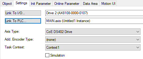
Property | Description | ||
|---|---|---|---|
Link to I/O… | The Link button opens a dialog box for linking the MC axis to the drive hardware under the I/O node. The linked item is displayed in the field to the right of it. | ||
Link to PLC… | The Link button opens a dialog box for linking the MC axis to a PLC instance of AXIS_REF. The linked item is displayed in the field to the right of it. | ||
Axis type | Specifies the protocol for communicating with the connected drive hardware. Details on the axis types can be found in Drive modules. | ||
Add. Encoder Type | Option to add an additional encoder to the axis. Details about the encoders can be found at Encoder modules. Example: Use this when connecting an Analog Drive that does not have its own encoder system. | ||
Task Context | Each axis must be assigned to a task context. If a MC Project has more than one context, you can use the combo box to change the axis's context. New contexts are created and configured using the MC Project's Context tab. | ||
Simulation |
|
| If simulation mode is active, the link to the I/O is ignored, and a simulation object (drive and encoder) is used instead of the configured axis type. |
| If the Axis Type is set to (none), the axis is always a simulation axis, and the setting cannot be changed. | ||
|
| The configured Axis Type and the link to the I/O are used. | |


