Example "Couple planar mover to track and moving it with DynamicsReductionMode"
Using these instructions, you will create a TwinCAT project that contains a planar mover and a planar track with a curve. The mover is coupled to the track and moved with the "AccelerationLimitedVelocity" option of the DynamicsReductionMode.
Creating a Planar mover
- See Configuration.
- 1. Create a Planar mover.
- 2. Put "Parameter (Init)" into simulation mode (TRUE). The parameter is hidden and only becomes visible if the "Show Hidden Parameters" checkbox is activated.
Creating a Planar track
- 3. Add the Planar track via Groups > Add New Item…, see Configuration.
Creating a PLC
- See preliminary steps under Creating a PLC.
- 1. Create the desired number of movers ("MC_PlanarMover") and tracks ("MC_PlanarTrack") via MAIN.
- These represent movers and tracks in the MC Configuration.
- 2. As shown below, create a planar mover, a planar track, a state variable for a state machine as well as two auxiliary positions and a variable for the approximate curve radius of the track.
Declare a feedback to be able to monitor the course of the command and an option variable to adjust the DynamicsReductionMode.
In addition, create three auxiliary variables to measure the time required and one auxiliary variable to check the maximum speed in the curve.
PROGRAM MAIN
VAR
    mover : MC_PlanarMover;
    track : MC_PlanarTrack;
    state : UDINT := 0;
    pos1, pos2 : PositionXYC;
    approx_radius : LREAL := 10;
    feedback : MC_PlanarFeedback;
    options : ST_MoveOnTrackOptions;
    max_velo_in_curve : LREAL := 0;
    start_time, end_time, elapsed_time : TIME;
END_VAR- 3. Then program a sequence in MAIN
- This program code creates and activates a track and both movers. Both movers are then coupled to the track and moved.
CASE state OF
    pos1.SetValuesXY(0, 0);
    pos2.SetValuesXY(400, 0);
    track.AppendLine(0, pos1, pos2);
    pos1.SetValuesXY(400 + approx_radius, approx_radius);
    pos2.SetValuesXY(400 + approx_radius, 400 + approx_radius);
    track.AppendLine(0, pos1, pos2);
    track.Enable(0);
    state := 1;
  1:
    IF track.MCTOPLC_STD.State = MC_PLANAR_STATE.Enabled THEN
      state := 2;
    END_IF
  2:
    mover.Enable(0);
    state := 3;
  3:
    IF mover.MCTOPLC.STD.State = MC_PLANAR_STATE.Enabled THEN
      state := 4;
    END_IF
  4:
    mover.JoinTrack(0, track, 0, 0);
    state := 5;
  5:
    IF mover.MCTOPLC.STD.CommandMode = MC_PLANAR_MOVER_COMMAND_MODE.OnTrack THEN
      state := 6;
    END_IF
  6:
    options.dynamicMode := MC.MC_DYNAMICS_REDUCTION_MODE.AccelerationLimitedVelocity;
    mover.MoveOnTrack(feedback, 0, track.GetLength(), 0, options);
    start_time := TIME();
    state := 7;
  7:
    IF mover.MCTOPLC.SETONTRACK.SetPos >= 400.0
    AND mover.MCTOPLC.SETONTRACK.SetPos <= 400.0 + PI*approx_radius/2
    AND mover.MCTOPLC.SETONTRACK.SetVelo > max_velo_in_curve THEN
      max_velo_in_curve := mover.MCTOPLC.SETONTRACK.SetVelo;
    END_IF

    IF mover.MCTOPLC.SETONTRACK.SetPos >= track.GetLength()-1.0
    AND NOT mover.MCTOPLC.STD.Busy.busyMover THEN
      state := 8;
    END_IF
  8:
    end_time := TIME();
    elapsed_time := end_time - start_time;
    state := 9;

END_CASE
Sending the command
- 4. To send the command, you must call the movers and the track cyclically with their update method after the END_CASE:
mover.Update();
track.Update();
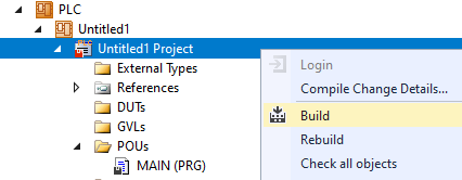
feedback.Update();Building the PLC creates symbols of the "PLC mover" and “track”, which can then be linked to the mover and track instance in the MC project.
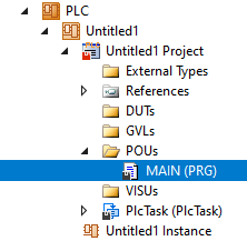
- 1. To build, use the path PLC > Untitled1 > Untitled1 Project > Build.
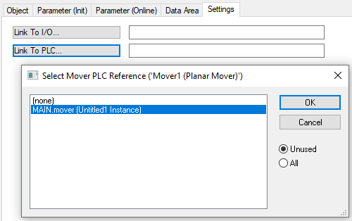
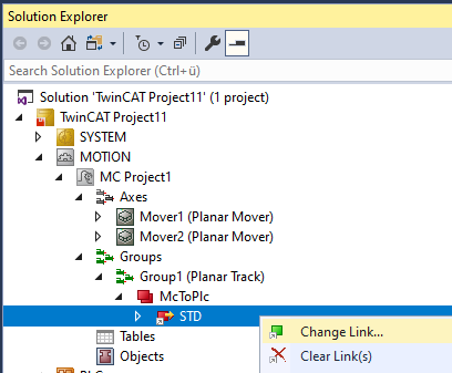
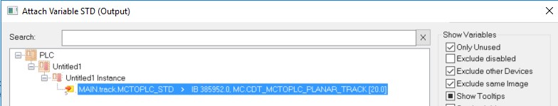
- Subsequently, the Planar movers in the “MC Project” can be linked with the Link To PLC... button on the Settings tab.
- The track must be linked separately via the following dialog boxes.
Activating and starting the project
- 1. Activate the configuration via the button in the menu bar
 .
. - 2. Set the TwinCAT system to the "Run" state via the button
 .
. - 3. Log in the PLC via the button in the menu bar
 .
. - 4. Start the PLC via the Play button in the menu bar.
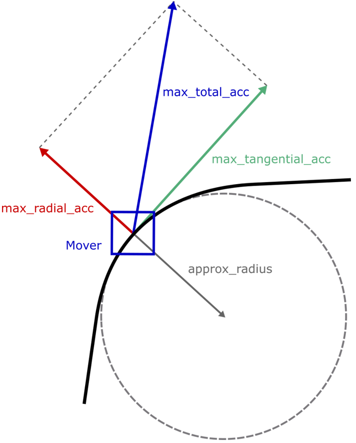
In this example, a track is created that contains a curve that is parameterized by the approximated radius "approx_radius". The mover moves along this track, whereby the dynamics are limited to a speed that ensures that the maximum radial acceleration is not exceeded.
This maximum radial acceleration "max_radial_acc" is set in the mover configuration via the "A" acceleration values of the "Maximum Dynamic X/Y" parameter. Both values must be the same, otherwise the command will be rejected. The parameters can be written using ADSWRITE, as in the example above.
As before, the tangential acceleration "max_total_acc" is parameterized directly on the movement command. The maximum total acceleration "max_total_acc" results from the specified maximum radial and tangential accelerations. This can be greater than either of the two individual accelerations.
In the example, the maximum speed within the curve is monitored and saved during the movement. As soon as the mover reaches the end of the track, the elapsed time is measured. Changes to the parameters for the radial acceleration "Maximum dynamic X/ Maximum dynamic Y", the approximated curve radius "approx_radius" and the "DynamicsReductionMode" influence both the time "elapsed_time" required for the movement along the track and the maximum speed in the curve "max_velo_in_curve".