5D-Kinematics Type 2 (XYZab)
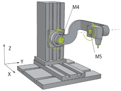
The 5D-Kinematics Type 2 (XYZab) are configured as shown in the drawing above.
The motors M1 to M3 (X, Y, Z) are scaled in millimeters. The motors M4 and M5 are scaled in degrees. The 0° position is the axis position shown in the drawing; the arrows indicate the positive direction of rotation.
 | Difference of Type 2 The 5D-Kinematics Type 2 differ from the 5D-Kinematics Type 3 in the orientation of the positive direction of axis rotation around the motor axes M4 and M5. |
Parameters for the Kinematics
Parameter | Description | Type | Unit |
|---|---|---|---|
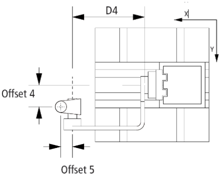
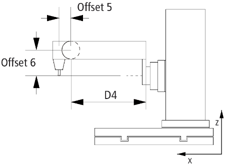
Handle D4 | Arm length in X-direction between motor axis 4 and motor axis 5 as shown in the drawing. |
| mm |
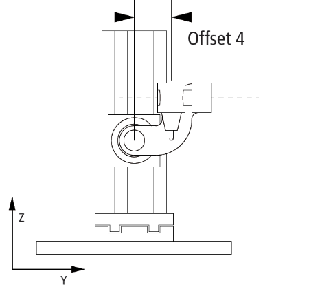
Offset 4 | Offset in y-direction between motor axis 4 and TCP. |
| mm |
Offset 5 | Offset in X-direction between motor axis 5 and TCP. |
| mm |
Offset 6 | Offset in Z-direction between motor axis 4 and motor axis 5. |
| mm |
Tool offset OID | Object ID of a tool mounted on the kinematics flange. The flange coordinate system is rotated 180 |
|
|
General Parameters for the Kinematics
General parameters that apply to any kinematics are described in the following sections:
For all kinematics with tool also applies:
Requirements
Development Environment | Target System | TwinCAT Function |
|---|---|---|
TwinCAT V3.1.4018.26 | PC or CX (x86 or x64) | TF5113 TwinCAT 3 Kinematic Transformation (Level 4) |
| TF5113 | TwinCAT Kinematic Transformation L4 TF5113 | TwinCAT 3 Kinematic Transformation L4 is subject to legal restrictions and is not included in the TF5400.AdvancedMotionPack workload or included in the TF5400 TwinCAT Advanced Motion Pack Setup from the website. If required, please get in touch with your sales contact. |