General Parameters for the Kinematics
MCS Offset
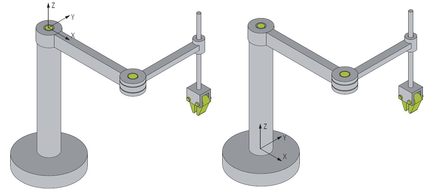
The MCS offset can be used to parameterize additional offset parameters before the first axis (or before the basis) of the kinematics. For example, in the SCARA kinematics the origin of the MCS is located in the first joint (M1). The parameter Z-shift of the MCS offset can be used to parameterize the additional bar length so that the origin of the MCS resides at the robot base.
Parameter | Description | Type | Unit |
|---|---|---|---|
X-shift | Static X-offset in the MCS. |
| mm |
Y-shift | Static Y-offset in the MCS. |
| mm |
Z-shift | Static Z-offset in the MCS. |
| mm |
MCS to Spatial reference
The MCS can be moved in a reference coordinate system using the Spatial reference parameter. All coordinate systems are right-handed (anticlockwise).
Parameter | Description | Type | Unit |
|---|---|---|---|
Translation X | Translation in X direction. |
| mm |
Translation Y | Translation in Y direction. |
| mm |
Translation Z | Translation in Z direction. |
| mm |
Rotation 1 | First rotation angle. The interpretation is defined by the parameter Rotation Convention. |
| ° |
Rotation 2 | Second rotation angle. The interpretation is defined by the parameter Rotation Convention. |
| ° |
Rotation 3 | Third rotation angle. The interpretation is defined by the parameter Rotation Convention. |
| ° |
Rotation convention | The rotation convention indicates the order of the axis rotations (parameter Rotation 1-3). The letters (X, Y, Z) from left to right indicate the order of the rotation around the corresponding axes. The number indicates the parameter (Rotation 1-3) for the value parameterization. The translation is always performed before the rotation. |
|
|
Spatial reference | The Spatial reference parameter indicates which coordinate system is used as basis for the MCS. If the value 0 is set here, the WCS is used as the basis. To use another coordinate system as starting point for the translation, a Coordinate Frame object can be created. The object ID of this coordinate system can be selected via the drop-down menu. |
|
|
Definition direction | Defines the direction in which the translation is programmed (from the point of view of the reference system or from the point of view of the MCS), see example below. |
|
|
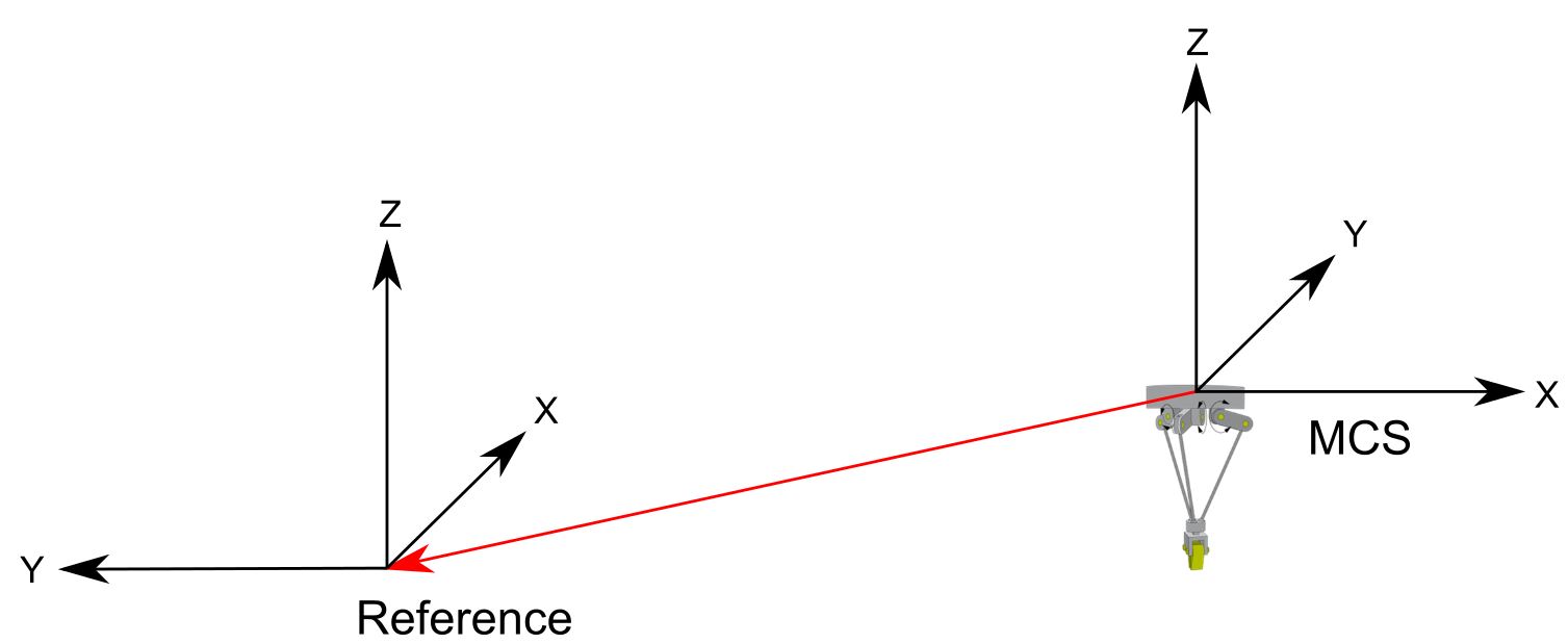
Example: Definition Direction
If the Definition Direction MCS -> Reference is used, the translation from the source coordinate system (MCS) to the target coordinate system (Reference) shown below is specified with negative vectors.
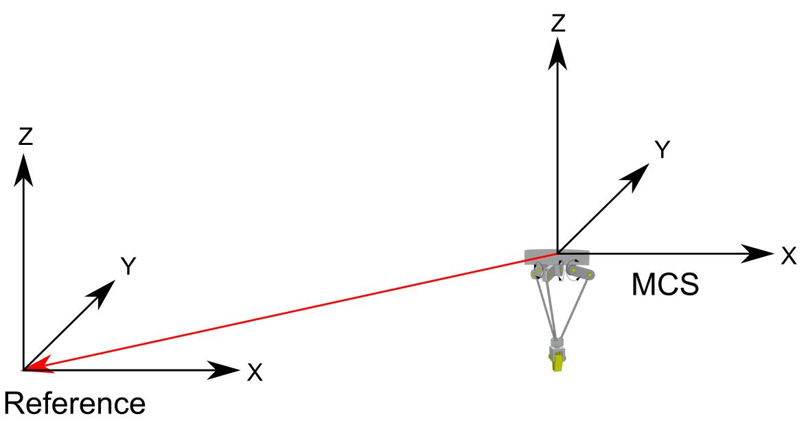
If a positive rotation around the Z-axis (here 90°) is specified in addition to the translation, the translation is carried out first and then the target coordinate system is rotated (here +90° around the Z-axis).
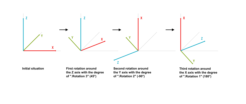
Example: Rotation
Parameter | Example values |
|---|---|
Rotation 1 | 180° |
Rotation 2 | -90° |
Rotation 3 | 45° |
Rotation convention | Rotation_Z3Y2_X1_DIN9300 |
Tool offset OID
Parameter | Description | Type |
|---|---|---|
Tool offset OID | To define a tool for the kinematics a Tool Offset object or a Tool Linear object has to be created at first. The object ID of this tool can be selected via the drop-down menu. |
|