Cartesian Tool Translation
Cartesian tool displacement refers to an offset between the reference point of the tool carrier and the reference point of the tool itself. In many cases, these reference points have the same location, so that a 0 can be entered for the tool displacement.
Parameter
The parameters for a translation are entered into the tool data in the same way as the tool length etc. Parameters 8 to 10 are available for this purpose. Here
- P8 always describes the X-component
- P9 always describes the Y-component
- P10 always describes the Z-component
independently of the choice of level.
Selecting and deselecting Cartesian tool displacement
As in the case of length compensation, tool displacement is switched on with D<n> (n>0). In order to travel to the translated location, the axes must at least be named. This means that the displacement affects the positioning when the axis is called for the first time. It is also possible for a new final position to be entered for the axis.
The function is switched off with D0. Here again, it is necessary for the axes at least to be named, if the axes are to travel to their new co-ordinates.
Sample 1:
N10 G17 G01 X0 Y0 Z0 F6000
N20 D1 X10 Y10 Z (Z-Axis is repositioned)
N30 ...
N90 M30
Sample 2:
N10 G17 G01 X0 Y0 Z0 F6000
N20 D1 X10 Y10 (Z-Axis is not moved)
N30 ...
N90 M30  | Using tool displacement and rotation If the Cartesian tool displacement is used in combination with rotation, then the compensation will only be correct if the aggregate (the tool carrier) is also rotated through the same angle. |
Application sample
It often happens that a processing machine's tool carrier contains a number of tools. The appropriate tool is pneumatically activated according to the kind of machining required. Since, however, the tools are located at different positions, Cartesian tool displacement is required.
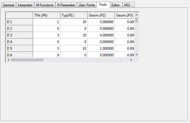
Tool parameters
Parameter | Value |
|---|---|
0 | 0..65535 |
1 | 10 |
2 | 40 |
5 | 0 |
8 | 100.0 |
9 | 0.0 |
10 | 50 |
Behavior with incremental dimension notation
Default behavior
If a new tool offset (and also length compensation) is selected in incremental dimensions (G91), then the compensation is applied once the axis is named.
Sample 3:
(Tooloffset D1: X10 Y20 Z30)
N10 G01 D1 X100 Y0 Z0 F6000
N20 G91 (incremental dimension)
N30 D2 (Tooloffset D2: X100
Y200 Z300)
N30 Z10
N40 ...
Command | Description |
ToolOffsetIncOn | The tool displacements and length compensations are also applied under G91 once the axis is named. (standard setting) |
ToolOffsetIncOff | The tool displacement and length compensation are not applied under G91. |
Sample 4:
(Tooloffset D1: X10 Y20 Z30)
N05 ToolOffsetIncOff
N10 G01 D1 X100 Y0 Z0 F6000
N20 G91 (incremental dimension)
N30 D2 (Tooloffset D2: X100
Y200 Z300)
N30 Z10
N40 ...
In N10 the Tooloffset is applied to all 3 axes. I.e. the axes move in the machine coordinate system (MCS) to X110 Y10 Z30.
In N30 the new Tooloffset of the Z-axis is not applied. This results in MCS X110 Y10 Z40.
See also ZeroShiftIncOn/Off