Rotation
It is also possible to program a rotation as well as the zero shift. A distinction is drawn between absolute and additive rotation.
The rotation can turn the co-ordinate axes (X, Y and Z) in the workpiece coordinate system.
This makes it possible to machine inclined surfaces (in the plane or in space).
Absolute Rotation
|
Command |
ROT X<value(x)> Y<value(y)> Z<value(z)> |
|
Cancellation |
ROT (without parameters) |
The rotation instructions must be programmed in their own block. Angles must always be stated in degrees.
Direction of Rotation
A positive angle describes rotation in the direction of the positive co-ordinate axis, the rotation being anti-clockwise.
Carrying Out the Rotation
The sequence of rotations is of critical importance when a coordinate system is being rotated. In TwinCAT NC I rotations are always carried out in the following sequence around the global coordinate system:
- Rotation around the Z-axis,
- Rotation around the Y-axis,
- Rotation around the X-axis.
This sequence is maintained even if the parameters are programmed in a different order.
The origin of the tool coordinate system is always used as the center point of the rotation. This means that the total zero offset shift currently active describes the rotation center.
Additive Rotation
In addition to absolute programming of rotation it is also possible to carry this out additively. The same conditions apply to this as do to absolute rotation.
|
Command |
AROT X <Wert(x)> Y<Wert(y)> Z<Wert(z)> |
|
Cancellation |
ROT (without parameters) |
Sample:
N10 G01 G17 X0 Y0 Z0 F60000
N20 G55
N30 G58 X200 Y0
N50 L47
N60 G58 X200 Y200
N65 ROT Z30
N70 L47
N80 G58 X0 Y200
N90 AROT Z15
N100 L47
N110 M30
L47
N47000 G01 X0 Y0 Z0 (movements for zero shift & rotation)
N47010 G91 (incremental dimensions)
N47020 G01 X100
N47030 G01 Y80
N47040 G03 X-20 Y20 I-20 J0
N47050 G01 X-40
N47060 G01 Y-40
N47070 G01 X-40 Y-30
N47080 G01 Y-30
N47090 G90
N47100 M17 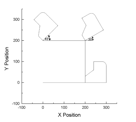
In this example, the same contour is traversed under different rotations. Since the contour (L47) is programmed in incremental dimensions, and the starting point is described by means of the programmed zero shift, the rotation is clear to see.
Note:
Once the ROT or AROT command has been programmed, the complete path vector (X, Y & Z) must be assigned.
Rotation extensions
In the default configuration the whole path vector must be programmed after each ROT command. Since this is difficult to realize in some applications, this calculation can optionally be performed automatically in the interpreter. To use this option, 'RotExOn' should be included at the start of the NC program.
|
Command |
RotExOn |
|
Cancellation |
RotExOff |
Sample:
N10 RotExOn
...
N100 G54 (activate zero point & point of rotation)
N110 ROT X90
N120 G0 Z3 (preposition the tool)
N130 G01 Z-10 F6000 (lower to cutting depth)
N140 G01 X100
N150 G01 Z3 (raise to preposition)
...
N1000 RotExOff
N1010 M30
Calculate rotation
|
Command |
CalcRot[ R<s>; R<t>; R<u>] |
|
|
CalcInvRot[ R<s>; R<t>; R<u>] |
|
Parameter |
The 3 R-parameters describe the vector to be calculated. The calculation will write the result into this R-parameter, and the original value will therefore be overwritten. |
The function CalcRot rotates a three-dimensional vector through the current rotation angle. The rotation angles had been determined by ROT or AROT. The sequence of the calculation is the same as is used for the rotation itself, that is Z, Y and X.
The CalcInvRot function behaves in precisely the opposite way. The signs of the currently valid rotation angles are inverted, and the order of calculation is X, Y and Z. In other words, the vector is turned back, so to speak.
Neither CalcRot nor CalcInvRot generate any geometry, but merely carry out the calculation of the vector.
Sample:
N10 G01 X40 Y10 Z0 F6000 (the axes are moved
without rotation)
N20 R1=40 R2=10 R3=0

N30 ROT Z45

(What is the position to which X, Y, must be taken so that no
movement is executed?)
N40 CalcInvRot[R1; R2; R3]
N50 G01 X=R1 Y=R2 Z=R3 (R1=35.35 R2=-21.21 R3=0)
N60 ... |
Command |
RotVec[ R<x>; R<y>; R<z>; R<α>; R<β>; R<γ>] |
|
Parameter |
The 3 R-parameters (x..z) describe the vector to be rotated through. The calculation will write the result into this R-parameter, and the original value will therefore be overwritten. |
The function RotVec rotates a three-dimensional vector through the specified angle. The order of the rotation is Z, Y and X, like for ROT. RotVec is a calculation routine solely for rotating a vector. It has no effect on ROT or AROT.