Tool Data
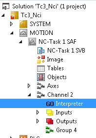
The NC has 255 memory locations (D1..D255) available for each channel for tool data. The parameters for the tool data can be written directly in the XAE. The data is saved as an ASCII file (<channel ID>.wz) which is kept in the TwinCAT\CNC directory. These files are automatically loaded when TwinCAT is started.
Currently two tool types are supported:
- Drills
- Shaft Cutters
The relevant columns (parameters) for this type of tool are described below.
Drills
Parameter | Meaning |
|---|---|
0 | Tool number |
1 | Tool type |
2 | Geometry: Length |
5 | Wear: Length |
8 | Cartesian tool displacement in X direction |
9 | Cartesian tool displacement in Y direction |
10 | Cartesian tool displacement in Z direction |
Shaft Cutters
Parameter | Meaning |
|---|---|
0 | Tool number |
1 | Tool type |
2 | Geometry: Length |
4 | Geometry: Radius |
5 | Wear: Length |
7 | Wear: Radius |
8 | Cartesian tool displacement in X direction |
9 | Cartesian tool displacement in Y direction |
10 | Cartesian tool displacement in Z direction |
Writing of tool data
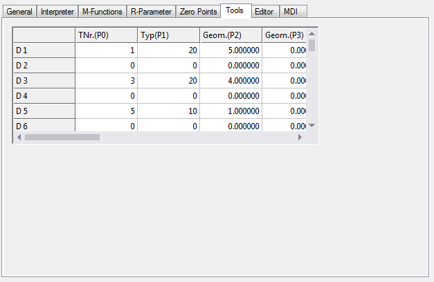
Editing tool data with the XAE
As already mentioned, the tool data can be written directly from the XAE. To do this, edit the window shown above.
Parameterization of tool data via the PLC
In addition, tool data can be read and written from the PLC with the function block ItpWriteToolDescEx.
Writing tool data from the parts program
In some applications, it is more convenient to write the tool data directly from the part program.
The tool set to be overwritten must not be active during the write process. This means, for example, if tool radius compensation with parameter set D10 is active, this cannot be overwritten, as long as D10 is still selected.
|
Command |
#set ToolParam(<Zeile>; <Spalte>;<Wert>)# |
|
Parameter <line> |
Describes the tool parameter line (1..255) |
|
Parameter <column> |
Column to be written (0..15) |
|
Parameter <value> |
Parameter value to be transmitted |
Sample:
N10 G0 X0 Y0 Z0
N20 G01 X100 F60000
N30 R1=10 R2=4 R3=20.3
N40 #set ToolParam(10; 0; 5)# #set ToolParam(10;1;20)#
N50 #set ToolParam(R1; R2; R3)#
N60 G41 X200 Y D10
...
Reading tool data from the parts program
This command can be used to assign tool data to an R-parameter.
|
Command |
#get ToolParam(<line>; <column>;<R-Param>)# |
|
Parameter <line> |
Writes to the tool parameter line (1..255); this corresponds to the D number |
|
Parameter <column> |
Column to be written (0..15) |
|
Parameter <R-Param> |
R-parameter in which the date is entered |
Sample:
N10 G0 X0 Y0 Z0
N20 G01 X100 F60000
N30 R1=10 R2=4
N40 #get ToolParam(10; 0; R5)# #getToolParam(10;1;R20)#
N50 #get ToolParam(R1; R2; R3)#
N60 G41 X200 Y D10
...
Notes: