Simulation
Lighting technology applications have become increasingly extensive and complex in recent years. On the one hand, the demands for more flexibility have increased and, on the other hand, additional performance features such as Tunable White (color temperature control), dynamic scene management or diagnostic functions have been added. At the same time, the time and effort required to create the application program and commission the system should be kept to a minimum.
By simulating the DALI devices used, an application program can be completely created, extensively tested and optimized even before commissioning. Deficits in the design of the hardware are detected at an early stage and cost-intensive conversion measures are prevented. The effort for commissioning at the real plant is reduced.
In addition to the preparation of commissioning, the simulation blocks are also well suited for training or presentations. Thus, even larger DALI lines can be mapped without the need for additional hardware. The simulation blocks are also a prerequisite for automated testing of function blocks (unit tests).
The Tc3_DALI library provides function blocks for simulating DALI lines with the associated DALI control gears. The simulation is completely transparent for the application program.
Simulated DALI lines are mapped by the function block FB_DALIVirtualCommunication. As with FB_KL6811Communication, FB_KL6821Communication and FB_EL6821Communication, FB_DALIVirtualCommunication also creates one instance per DALI line and calls it cyclically in a fast task.
fbDALISimulationCommunication : FB_DALIVirtualCommunication;This instance is passed to the respective application function blocks.
fbDimmer2Switch : FB_DALI102Dimmer2Switch(Communication.fbDALISimulatedCommunication);The individual DALI control gears are represented by the function block FB_DALIVirtualControlGear. One instance is required per DALI control gear. The individual parameters such as short address, group assignments, scenes, etc. are set via Properties. When the instances are declared, they are also assigned to the simulated DALI line.
fbSUT : ARRAY [1..6] OF FB_DALIVirtualControlGear(fbVirtualCommunication) :=
 [(nShortAddress := 0, nGroups := 2#0010_0000_0100_1100, nMaxLevel := 254, nMinLevel := 85),
  (nShortAddress := 1, nGroups := 2#0000_0100_0000_0000, nMaxLevel := 254, nMinLevel := 85),
  (nShortAddress := 2, nGroups := 2#0000_0100_0000_0000, nMaxLevel := 254, nMinLevel := 85),
  (nShortAddress := 3, nGroups := 2#0000_0000_0100_1111, nMaxLevel := 254, nMinLevel := 85),
  (nShortAddress := 4, nGroups := 2#0010_0000_0000_1010, nMaxLevel := 254, nMinLevel := 85),
  (nShortAddress := 5, nGroups := 2#0010_0100_0000_0100, nMaxLevel := 254, nMinLevel := 85)];
The properties can be changed at runtime of the simulation. Hereby e.g. error states can be simulated (see property bLampFailure) and the behavior of the application can be checked for these errors.
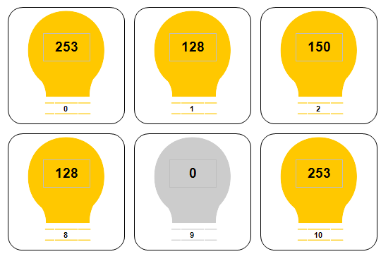
For the visual representation of the individual simulated DALI control gears, the TwinCAT PLC HMI can be used, for example. For this purpose, the ready-to-use sample application DALI PLC Simulation Tool is provided.