FB_BA_PIDCtrl
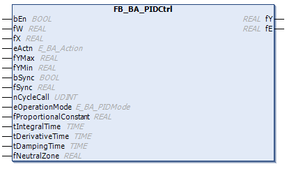
The FB_BA_PIDCtrl function block is a universal PID controller.
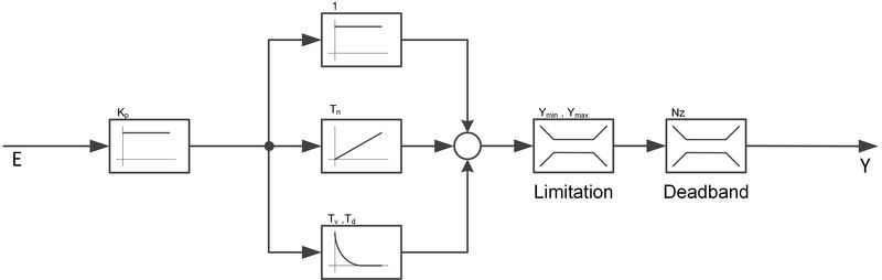
The controller is divided internally into two consecutive parts:
- the controller itself, illustrated in the functional diagrams below as P, I and D part with an output limitation.
- a deadband element (neutral zone) that applies a hysteresis to the output changes of the controller.
Operation mode "Upstream P part":
(eOperationMode = E_BA_PIDMode.eP1ID)
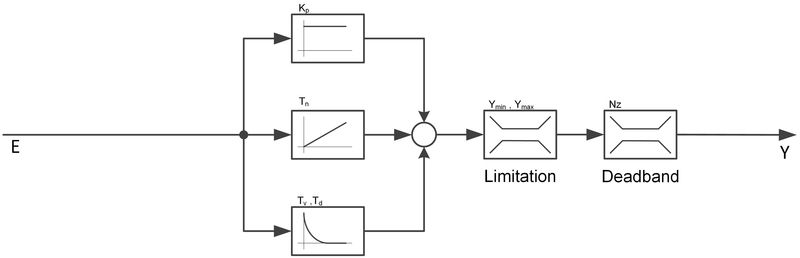
"Parallel structure" operation mode:
(eOperationMode = E_BA_PIDMode.ePID )
Control direction
If bActn = FALSE, the control direction of the controller is reversed so that a control deviation of less than 0 causes a change in the control value in the positive direction. This is achieved by a negative calculation of the control deviation:
bActn | fE (control deviation) | Control direction |
|---|---|---|
TRUE | fX-fW (actual value-setpoint) | direct (cooling) |
FALSE | fW-fX (setpoint-actual value) | indirect (heating) |
Passive behavior (bEn = FALSE)
The outputs are set as follows:
fY | 0.0 |
fE | current control deviation, see control direction. |
The internal values for the P, I, and D parts are set to 0, also the values for the I and D parts of the preceding cycle. In case of a restart the control value is thus calculated in the first cycle without past values.
Active behavior (bEn = TRUE)
In the first cycle, the I and D parts are calculated without historical values, as already mentioned.
Anti-Reset-Windup
If the I part is active, the controller ensures that it is retained, if the controller output rY is about to move beyond the limits fYMin or fYMax. A preliminary calculation of the controller output takes place inside the controller in every cycle.
Anti-reset windup at min limit
If the precalculation is smaller than the lower output limit fYMin, the I part is prevented from falling further and is limited to the value of the last PLC cycle. However, an increase in the I part remains possible.
Anti-reset windup at max limit
On the other hand, if the precalculation is greater than the upper limit fYMax, the I part is prevented from increasing further and is also limited to the value of the last PLC cycle. In this case, a drop in the I part remains possible.
Synchronizations
There are several cases where controller output must not only be limited, but also synchronized to a new value by manipulating the I part (if not active, then the D part or the P part). These cases are prioritized because of the potential for simultaneity:
Prio | Description | Conditions | Comments |
|---|---|---|---|
1 | Synchronization via bSync/fSync | Controller enabled - bEn = TRUE | A positive signal on bSync sets the I part so that the control value assumes the value fSync. If bEn and bSync are set at the same time, this method can be used to set an initial value from which the controller starts. If the I part is not active, the D part is set accordingly. Note that only the rising edge of bSync is evaluated internally as this is a setting action. A TRUE signal must be applied again to the input bSync for renewed synchronization, for instance with a transfer value. |
2 | Range synchronization fYMin | Controller enabled - bEn = TRUE fYMin <> fYMin_1 (last cycle) fY_Test < fYMin | If the lower range limit has changed and the precalculated controller output is now smaller than fYMin then synchronization is performed to fYMin. |
3 | Range synchronization fYMax | Controller enabled - bEn = TRUE fYMax <> fYMax_1 (last cycle) fY_Test > fYMax | if the upper range limit has changed and the precalculated controller output is now greater than fYMax, then synchronization is performed to fYMax |
4 | Synchronization with reversal of the control direction | Controller enabled - bEn = TRUE eActn <> eActn_1 (last cycle) | It is synchronized so that the output holds the value BEFORE the reversal: |
5 | Anti-Reset-Windup | Controller enabled - bEn = TRUE | see Anti-Reset-Windup |
Neutral zone
A value of fNeutralZone > 0.0 enables the function of the neutral zone (deadband). A value equal to zero deactivates the deadband element and the values at the input are passed directly through.
If, for the active controller, the change at the input of the element in a PLC cycle is smaller than fNeutralZone / 2 in comparison with the previous PLC cycle, then the output is held at the value of the previous cycle until the change is larger than or equal to fNeutralZone / 2.
This function is intended to avoid an unnecessarily large number of actuating pulses.
Syntax
VAR_INPUT
  bEn                      : BOOL;
  fW                       : REAL;
  fX                       : REAL;
  eActn                    : E_BA_Action := E_BA_Action.eReverse;
  fYMax                    : REAL := 100;
  fYMin                    : REAL := 0;
  bSync                    : BOOL;
  fSync                    : REAL;
END_VAR
VAR_INPUT CONSTANT PERSISTENT
  nCycleCall               : UDINT := 5;
  eOperationMode           : E_BA_PIDMode := E_BA_PIDMode.eP1ID;
  fProportionalConstant    : REAL;
  tIntegralTime            : TIME;
  tDerivativeTime          : TIME;
  tDampingTime             : TIME;
  fNeutralZone             : REAL := 0.0;
END_VAR
VAR_OUTPUT
  fY                       : REAL;
  fE                       : REAL;
END_VAR
Inputs
Name | Type | Description |
|---|---|---|
bEn | BOOL | Enable of the controller. |
fW | REAL | Setpoint of the controlled system. |
fX | REAL | Actual value of the controlled system. |
eActn | Control direction of the controller. | |
fYMax | REAL | Upper output limit of the controller [%]. |
fYMin | REAL | Lower output limit of the controller [%]. |
bSync | BOOL | Synchronizes the controller to the value of fSync. |
fSync | REAL | Synchronization value. The value fSync is internally limited to values from fYMin to fYMax. |
Inputs CONSTANT PERSISTENT
Name | Type | Description |
|---|---|---|
nCycleCall | UDINT | Call cycle of the function block as a multiple of the cycle time. Internally limited to a minimum value of 1. |
eOperationMode | Mode of operation of the controller: PID mode or P-ID mode | |
fProportionalConstant | REAL | Controller gain. Only affects the P part. Internally limited to a minimum value of 0. |
TIntegralTime | TIME | Integral action time of the I part [ms]. A null value at this parameter disables the I part. |
tDerivativeTime | TIME | Rate time of the D part [ms]. A null value at this parameter disables the D part. |
tDampingTime | TIME | Damping time of the D part [s]. |
fNeutralZone | REAL | Dead zone |
 Outputs
Name | Type | Description |
|---|---|---|
fY | REAL | Control value. Range limited by fYMin and fYMax. |
fE | REAL | Control deviation (The calculation depends on the control direction). |
Requirements
Development environment | Required PLC library |
|---|---|
TwinCAT 3.1 4024.35 | Tc3_BA2_Common from V2.1.20.0 |