MP_UST_3
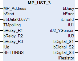
This function block is used to control and monitor a multi-I/O module UST3.
MP_Address is used to specify the MP-Bus device with which the function block is to communicate. bStart activates communication with the MP-Bus device. bBusy indicates that the function block is active. If bStart remains TRUE, the device is addressed cyclically with a period specified by the time in TMPolling. The time must be set greater than one second. bError indicates an error in communication with the actuator. The type of the error can be read with iErrorID.
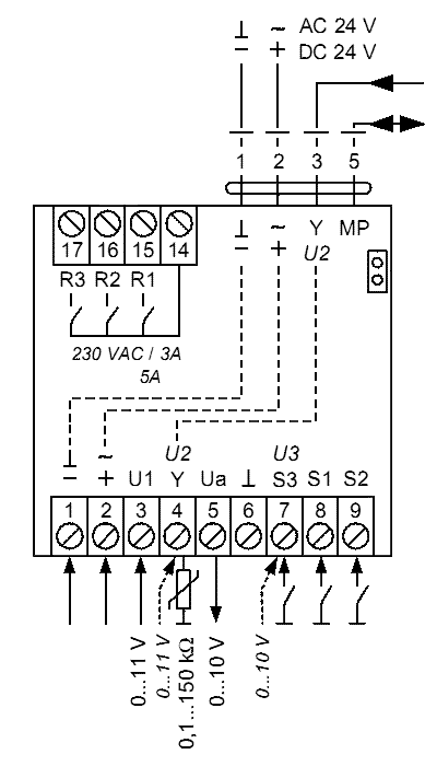
The input data bRelay_R1 to bRelay_R3 switch the relays R1 to R3 (PIN 15 to PIN 17). The variable iUa switches the analog output 0…10 V to PIN 5. One digit corresponds to 1 mV.
The SETTINGS data structure is used for parameterization of the UST3. The scaling of the analog input data can be set, and the resistance measurement can be enabled on PIN4. The scaling of the measured resistance value can be changed for the resistance measurement. This can also be done while the system is running. iU1 is the analog input on pin 3. One digit corresponds to one mV. If the scaling in the SETTINGS data structure is changed, one digit corresponds to 250 µV.
The same applies to the analog inputs iU2_YSensor (PIN 4) and iU3 (PIN 7). The iU2_YSensor can also be used for resistance measurement. This must be set via the SETTINGS data structure. bDigital_S1 to bDigital_S3 correspond to the digital inputs of the UST3, PIN 7 to PIN 9.
All data is automatically polled by the KL6771. The polling speed depends on the number of connected MP-Bus devices and the set polling time. The digital inputs are unsuitable for connecting buttons or sensors that only emit short pulses. In order to reliably detect a change in the signal level, the change must last at least one second.
 Inputs
VAR_INPUT
  MP_Address     : USINT := 1;
  bStart         : BOOL;
  strDataKL6771  : DataKL6771;
  TMpolling      : TIME := t#10s;
  bRelay_R1      : BOOL;
  bRelay_R2      : BOOL;
  bRelay_R3      : BOOL;
  iUa            : UINT;
  SETTINGS       : UST3_SET;
END_VAR
Name | Type | Description |
|---|---|---|
MP_Address | USINT | MP-Bus address of the slave. |
bStart | BOOL | A positive edge starts the function block. If this remains continuously TRUE, the function block will be activated cyclically with a period specified by the time in TMPolling. |
strDataKL6771 | The data structure with which the KL6771() function block must be linked. | |
TMpolling | TIME | The time for which the function block should address the actuator. Default 10 s, minimum time 1 s. |
bRelay_R1 | BOOL | Relay PIN 15 |
bRelay_R2 | BOOL | Relay PIN 16 |
bRelay_R3 | BOOL | Relay PIN 17 |
iUa | UINT | Analog output PIN 5 (1 mV = 1 digit) |
SETTINGS | Data structure for setting the scaling and the resistance measurement. |
 Outputs
VAR_OUTPUT
  bBusy          : BOOL;
  bError         : BOOL;
  iErrorId       : MP_Error;
  iU1            : INT;
  iU2_YSensor    : INT;
  iU3            : INT;
  bDigital_S1    : BOOL;
  bDigital_S2    : BOOL;
  bDigital_S3    : BOOL;
  iResistor      : INT;
END_VAR
Name | Type | Description |
|---|---|---|
bBusy | BOOL | This bit is set for as long as the function block is active. |
bError | BOOL | This output goes TRUE as soon as an error occurs. This error is described via the iErrorId variable. |
iErrorId | This output outputs an error code in the event of an error. bError goes TRUE at the same time. | |
iU1 | INT | analog input PIN 3 (1 digit = 1 mV or 1 digit = 250 µV) |
iU2_YSensor | INT | analog input PIN 4 (1 digit = 1 mV or 1 digit = 250 µV) |
iU3 | INT | analog input PIN 7 (1 digit = 1 mV or 1 digit = 250 µV) |
bDigital_S1 | BOOL | digital input PIN 8 |
bDigital_S2 | BOOL | digital input PIN 9 |
bDigital_S3 | BOOL | digital input PIN 7 |
iResistor | INT | Resistance value PIN 4 |
Requirements
Development environment | PLC library to include |
|---|---|
TwinCAT from v3.1.4020.14 | Tc2_MPBus from 3.3.5.0 |