Gear unit and motor
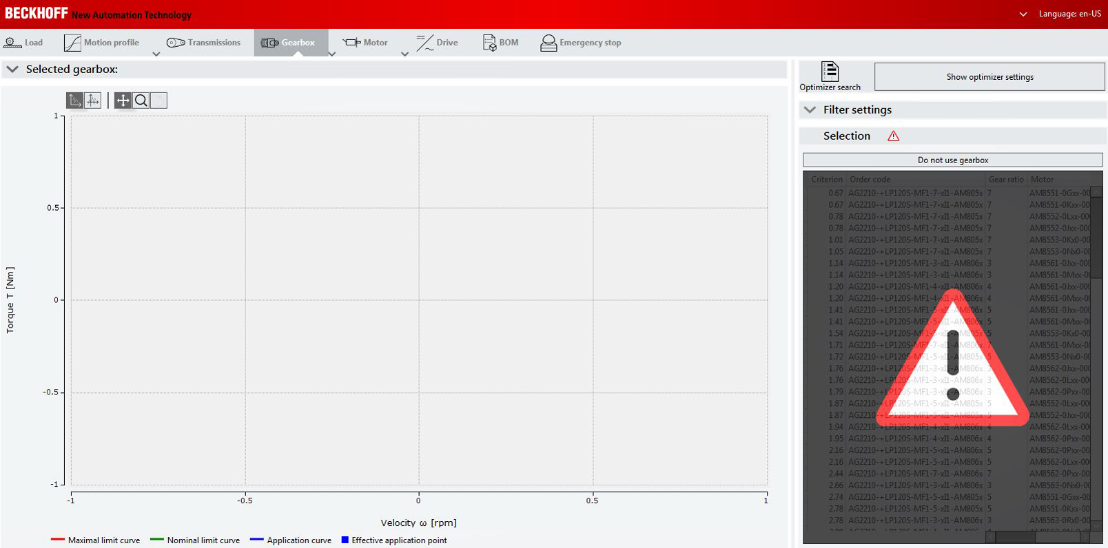
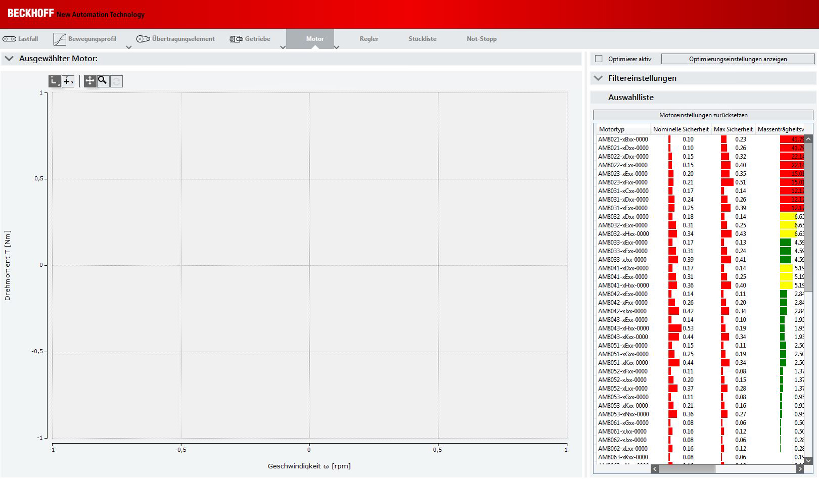
Once you have specified your components via manual selection or the optimizer, you can select them. The image on the left shows the user interface of the gear selection; the motor interface is shown on the right. When you click the button: “Use no gear unit" or "Reset motor setting", a red warning triangle appears (see image on the left), and the selection lists are hidden. | |
|
|
Gear unit and motor curve profiles
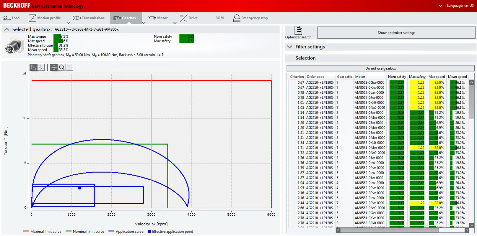
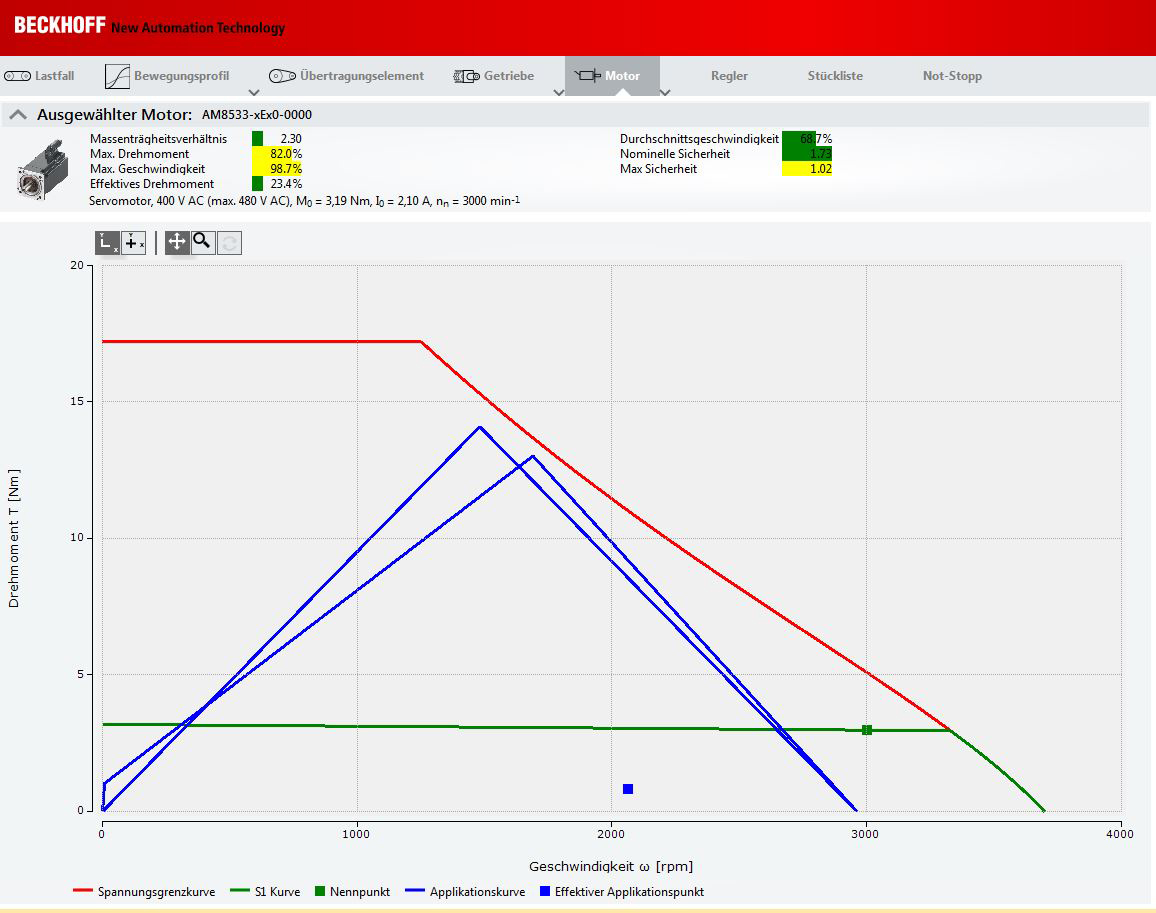
After the gear unit and motor selection, curves profiles of the components are displayed below. The profile definitions are explained in more detail in this chapter. | |
Curve profile of the selected gear unit | Curve profile of the selected motor |
|
|
S1 – curve (green line): Indicates the permitted mean drive speed and S5 – curve (red line): Indicates the maximum drive speed and the maximum acceleration torque in the form of periodically intermittent operation. The gear unit accelerates and decelerates periodically. Application curve (blue line): Indicates the speed and torque requirements for the specified motion profile. The application curve must always be in the range of the red S-5 curve (for gear units) or the red voltage limit curve (for motors). | Nominal point (green square): The rated point represents the rated torque at the rated speed. This depends on the set operating voltage. Effective application point (blue square): The effective application point is calculated from the application curve including standstill periods. It represents the mean speed and torque requirement. This point must always be within the green S1 curve.
|