ONLINE configuration creation
Detecting/scanning of the EtherCAT device
If the TwinCAT system is in CONFIG mode, you can search for devices online. This can be recognized by a symbol at the bottom right of the information bar:
- in the user interface of the TwinCAT 3 development environment by a symbol
 .
.
TwinCAT can be set in this mode:
- TwinCAT 3: by selecting from the menu bar or via "TWINCAT" → "Restart TwinCAT (Config Mode)"
 | Online scanning in Config mode The online search is not available in RUN mode (production operation). Note the differentiation between TwinCAT programming system and TwinCAT target system. |
The TwinCAT 3 icon () in the Windows taskbar always represents the TwinCAT mode of the local IPC. In contrast, the TwinCAT state of the target system is displayed in the System Manager window in the TwinCAT 3 user interface.
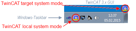 Fig.81: Differentiation between local system/target system (TwinCAT 3)
Right-clicking on “I/O Devices” in the configuration tree opens the search dialog.
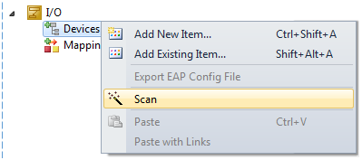 Fig.82: Scan Devices (TwinCAT 3)
This scan mode not only tries to find EtherCAT devices (or Ethernet ports that can be used as such), but also NOVRAM, fieldbus cards, SMB etc. Not all devices can be found automatically.
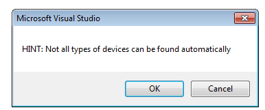 Fig.83: Note automatic device scan (TwinCAT 3)
Ethernet ports with installed TwinCAT real-time driver are shown as "RT Ethernet" devices. An EtherCAT frame is sent to these ports for testing purposes. If the scan agent detects from the response that an EtherCAT slave is connected, the port is immediately shown as an “EtherCAT Device” .
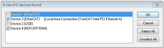 Fig.84: Detected Ethernet devices
 Devices can be selected using the corresponding checkboxes (e.g. device 3 and device 4 are selected as shown in the figure "Detected Ethernet devices"). After confirming with "OK", a device scan is suggested for all selected devices, see Fig. "Scan query after automatic creation of an EtherCAT device".
| Selection Ethernet port Ethernet ports can only be selected for EtherCAT devices for which the TwinCAT real-time driver is installed. This has to be done separately for each port. Please refer to the respective installation page. |
Detecting/Scanning the EtherCAT devices
| Online scan functionality During a scan the master queries the identity information of the EtherCAT slaves from the slave EEPROM. The name and revision are used for determining the type. The respective devices are located in the stored ESI data and integrated in the configuration tree in the default state defined there. |
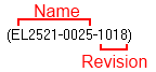 Fig.65: Example Default state
Notice | |
Slave scanning in practice in standard machine production The scanning function should be used with care. It is a practical and fast tool for creating an initial configuration as a basis for commissioning. In standard machine construction or when reproducing the system, however, the function should no longer be used to create the configuration but, if necessary, for comparison with the defined initial configuration. |
Example:
Company A builds the prototype of a machine B, which is to be produced in series later on. To do this the prototype is built, a scan of the I/O devices is performed in TwinCAT and the initial configuration ‘B.tsm’ is created. The EL2521-0025 EtherCAT terminal with the revision 1018 is located at any position. It is thus built into the TwinCAT configuration in this way:
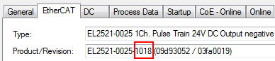 Fig.86: Installation EtherCAT Terminal with revision -1018
Likewise, during the prototype test phase, the functions and properties of this terminal are tested by the programmers/commissioning engineers and used if necessary, i.e. addressed from the PLC ‘B.pro’ or the NC. (the same applies analogously to the TwinCAT 3 solution files).
The prototype development is now completed and series production of machine B starts, for which Beckhoff continues to supply the EL2521-0025-0018. If the commissioning engineers of the standard machine production department always carry out a scan, a B configuration with the identical contents results again for each machine. Likewise, A might create spare parts stores worldwide for the coming standard machines with EL2521-0025-1018 terminals.
After some time Beckhoff extends the EL2521-0025 by a new feature C. Therefore the FW is changed, outwardly recognizable by a higher FW version and a new revision -1019. Nevertheless the new device naturally supports functions and interfaces of the predecessor version(s); an adaptation of ‘B.tsm’ or even ‘B.pro’ is therefore unnecessary. The standard machines can continue to be built with ‘B.tsm’ and ‘B.pro’; it makes sense to perform a comparative scan against the initial configuration ‘B.tsm’ in order to check the built machine.
However, if the series machine production department now doesn't use ‘B.tsm’, but instead carries out a scan to create the productive configuration, the revision -1019 is automatically detected and built into the configuration:
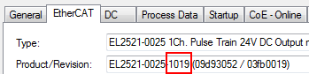 Fig.87: Recognizing EtherCAT Terminal with revision -1019
This is usually not noticed by the commissioning engineers. TwinCAT cannot signal anything either, since virtually a new configuration is created. According to the compatibility rule, however, this means that no EL2521-0025-1018 should be built into this machine as a spare part (even if this nevertheless works in the vast majority of cases).
In addition, it could be the case that, due to the development accompanying production in company A, the new feature C of the EL2521-0025-1019 (for example, an improved analog filter or an additional process data for the diagnosis) is discovered and used without in-house consultation. The previous stock of spare part devices are then no longer to be used for the new configuration ‘B2.tsm’ created in this way.
If standard machine production is established, the scan should only be performed for informative purposes for comparison with a defined initial configuration. Changes are to be made with care!
If an EtherCAT device was created in the configuration (manually or through a scan), the I/O field can be scanned for devices/slaves.
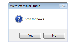 Fig.88: Scan query after automatic creation of an EtherCAT device (TwinCAT 3)
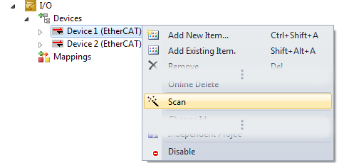 Fig.89: Manual triggering of a device scan on a specified EtherCAT device (TwinCAT 3)
In the user interface (TwinCAT 3), the scan process can be followed via the loading bar at the bottom of the status bar.
The configuration is established and can then be switched to online state (OPERATIONAL).
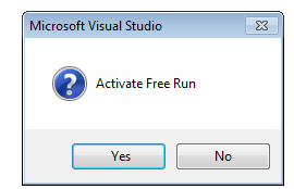 Fig.90: Config/FreeRun query (TwinCAT 3)
In Config/FreeRun mode the System Manager display alternates between blue and red, and the EtherCAT device continues to operate with the idling cycle time of 4 ms (default setting), even without active task (NC, PLC).
 Fig.91: Display of the change between "Free Run" and "Config Mode" at the bottom right of the status bar
 Fig.92: TwinCAT can also be switched to this state by using a button (TwinCAT 3)
The EtherCAT system should then be in functional cyclical operation as shown in Fig. Example online display.
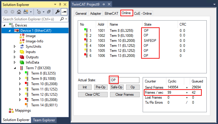 Fig.93: Example online display
 Please note:
- all slaves should be in OP state
- the EtherCAT master should be in “Actual State” OP
- "frames/sec" should match the cycle time taking into account the sent number of frames
- no excessive "LostFrames" or CRC errors should occur
The configuration is now complete. It can be modified as described under manual procedure.
Troubleshooting
Various effects may occur during scanning.
- An unknown device is detected, i.e. an EtherCAT slave for which no ESI XML description is available.
In this case the System Manager offers to read any ESI that may be stored in the device. This case is described in the chapter “Notes regarding ESI device description”. - Device are not detected properly
Possible reasons include: - faulty data links, resulting in data loss during the scan
- slave has invalid device description
- The connections and devices should be checked in a targeted manner, e.g. via the emergency scan.
Then re-run the scan.
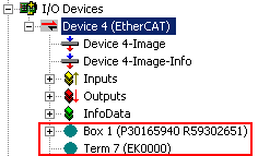 Fig.94: Faulty identification
In the System Manager such devices may be set up as EK0000 or unknown devices. Operation is not possible or meaningful.
Scan over existing Configuration
Notice | |
Change of the configuration after comparison With this scan (TwinCAT 2.11 or 3.1) only the device properties vendor (manufacturer), device name and revision are compared at present! A ‘ChangeTo’ or ‘Copy’ should only be carried out with care, taking into consideration the Beckhoff I/O compatibility rule (see above). The device configuration is then replaced by the revision found; this can affect the supported process data and functions. |
If a scan is initiated for an existing configuration, the actual I/O environment may match the configuration exactly or it may differ. This enables the configuration to be compared.
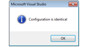 Fig.95: Identical configuration (TwinCAT 3)
If differences are detected, these are displayed in the correction dialog and the configuration can be adjusted immediately.
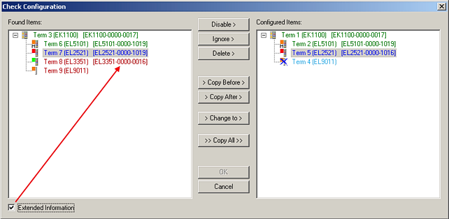 Fig.96: Correction dialog
 The display of "Extended Information" is recommended because it makes differences in the revision visible.
Color | Explanation |
|---|---|
green | This EtherCAT slave matches the entry on the other side. Both type and revision match. |
blue | This EtherCAT slave is present on the other side, but in a different revision. This other revision may have different default settings for the process data and different/additional functions. If the found revision is lower than the configured revision, it is likely that the use is not possible. The found devices may not support all functions that the master expects based on the higher revision number. |
light blue | This EtherCAT slave is ignored (“Ignore” button) |
red |
|
| Device selection based on revision, compatibility The ESI description also defines the process image, the communication type between master and slave/device and the device functions, if applicable. The physical device (firmware, if available) has to support the communication queries/settings of the master. This is backward compatible, i.e. newer devices (higher revision) should be supported if the EtherCAT master addresses them as an older revision. The Beckhoff compatibility rule for EtherCAT Terminals/ Box modules/ EJ modules is to be assumed: |
Example
An EL2521-0025-1018 is specified in the configuration, then an EL2521-0025-1018 or higher (-1019, -1020) can be used in practice.
Fig.65: Name/Revision Terminal If current ESI descriptions are available in the TwinCAT system, the last revision offered in the selection dialog matches the Beckhoff state of production. It is recommended to use the last device revision when creating a new configuration, if current Beckhoff devices are used in the real application. Older revisions should only be used if older devices from stock are to be used in the application.
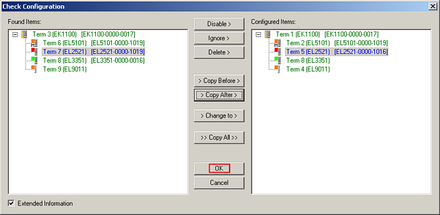 Fig.98: Correction dialog with modifications
 Once all modifications have been saved or accepted, click "OK" to transfer them to the real *.tsm configuration.
Change to Compatible Type
With "Change to Compatible Type...", TwinCAT offers a function for replacing a device while retaining the links in the task.
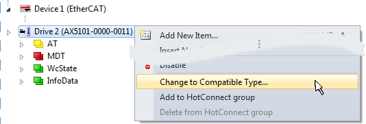 Fig.99: Dialog "Change to Compatible Type" (TwinCAT 3)
The following elements in the ESI of an EtherCAT device are compared by TwinCAT and assumed to be the same in order to decide whether a device is displayed as "compatible":
- Physics (e.g. RJ45, Ebus...)
- FMMU (additional ones are permitted)
- SyncManager (SM, additional ones are permitted)
- EoE (attributes MAC, IP)
- CoE (attributes SdoInfo, PdoAssign, PdoConfig, PdoUpload, CompleteAccess)
- FoE
- PDO (process data: sequence, SyncUnit SU, SyncManager SM, EntryCount, Entry.Datatype)
This function is used intensively in devices of the AX5000 family.
Change to Alternative Type
The TwinCAT System Manager offers a function for the exchange of a device: Change to Alternative Type
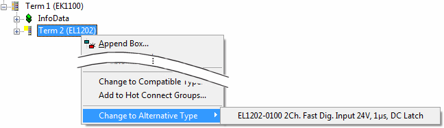 Fig.100: TwinCAT 2 Dialog Change to Alternative Type
If called, the System Manager searches in the procured device ESI (in this example: EL1202-0000) for details of compatible devices contained there. The configuration is changed and the ESI-EEPROM is overwritten at the same time – therefore this process is possible only in the online state (ConfigMode).