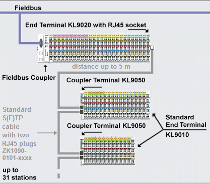
Structure of a K-bus extension
| |
Risk of injury through electric shock and damage to the device! Bring the Bus Terminals system into a safe, de-energized state before starting mounting, disassembly or wiring of the Bus Terminals! |

Mounting
When mounting, observe the information in the chapter entitled Mounting rail installation.
- Ensure that the system is powered down and in a safe state.
- Install the first bus terminal block, consisting of the fieldbus coupler and the desired Bus Terminals, on a mounting rail.
Instead of a standard End Terminal (KL9010), install an End Terminal with RJ45 socket (KL9020) as the last terminal at the end of the first Bus Terminal block. - Install the first expansion terminal block, consisting of a Coupler Terminal (KL9050) and the desired Bus Terminals, on a mounting rail.
Install a standard End Terminal (KL9010) as the last terminal at the end of the first expansion terminal block. - Connect one RJ45 plug of an Ethernet cable into the RJ45 socket of the KL9020 of the first bus terminal block until it clicks into place.
Connect the other RJ45 plug of the Ethernet cable into the RJ45 socket (labelled IN) of the expansion terminal block Coupler Terminal (KL9050) until it clicks into place. - Install the next expansion terminal block, consisting of a Coupler Terminal (KL9050) and the desired Bus Terminals, on a mounting rail.
Install a standard End Terminal (KL9010) as the last terminal at the end of this expansion terminal block. - Connect one RJ45 plug of an Ethernet cable into the RJ45 socket (labelled OUT) of the KL9020 of the previous expansion terminal block until it clicks into place.
Connect the other RJ45 plug of the Ethernet cable into the RJ45 socket (labelled IN) of the KL9050 of the added expansion terminal block until it clicks into place. - Repeat steps 5 and 6 in order to connect further expansion terminal blocks. A maximum of 31 expansion terminal blocks can be connected.
- Set the Function Switch on all Coupler Terminals (KL9050) correctly.
Function Switch
- Switch position Next:
The Function Switch of all Coupler Terminals (KL9050) to which a continuing Ethernet cable is connected must be set to position Next! - Switch position Last:
Activate the terminating resistor at the last expansion terminal block of your K-bus extension system by switching the Function Switch on the last Coupler Terminal (KL9050) to the Last position.
| |
Danger to persons, the environment and equipment
|
Notes on the topology
 | Notes on the connection of the KL9020 and KL9050 terminals The end terminal with RJ45 socket (KL9020) may only be used at the end of Bus Terminal blocks that are opened by a fieldbus coupler! All extension terminal blocks must be terminated by a KL9010 standard end terminal! At least one terminal with process image must be connected to each KL9050 Coupler Terminal! The operation of an extension terminal block with only one KL9010 (with no inputs or outputs) is not permissible |
Disassembly
When mounting, observe the information in the chapter entitled Mounting rail installation.
- Ensure that the system is powered down and in a safe state.
- Press the plastic lock of the RJ45 plug and pull it from the socket.
- Carefully pull the orange-colored lug approximately 1 cm out of the terminal to be disassembled, until it protrudes loosely. The lock with the C mounting rail is now released for this terminal, and the terminal can be pulled from the mounting rail without excessive force.
- Grasp the released terminal with thumb and index finger simultaneous at the upper and lower grooved housing surfaces and pull the terminal away from the mounting rail.