KL8001 Power terminal - Functional description
Rotary switches for adjusting the rated current
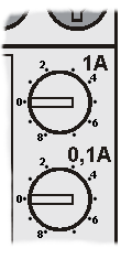
You can set the motor's rated current manually using the two rotary switches on the power terminal. The upper rotary switch operates in 1 A steps, while the lower switch provides 0.1 A steps. You can thus set values between 0.9 A and 9.9 A. The value set then applies to all three phases.
If you set the two rotary switches to zero, you must specify the rated motor current using the three parameter registers PR33, PR39 and PR45. You can then:
- set the rated current separately for each phase, if three different single-phase motors are connected, for example.
- use the extended setting range of 10.0 A to 15.0 A, which cannot be set via the rotary switches.
LEDs
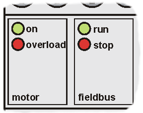
The power terminal has 4 LEDs for status display to enable rapid diagnosis. The possible states are listed in the following table.
LED | State | Description |
|---|---|---|
on (motor) | on | Motor is running, either to the right or left |
off | Motor is switched off, or overload protection has triggered | |
overload (motor) | on | Motor has been switched off due to overload |
flashes (2 Hz) | Power has fallen below minimum load threshold | |
flashes (5 Hz) | Overload threshold has been exceeded | |
off | Nominal operation (load neither below minimum and or above maximum), or motor is switched off | |
run (fieldbus) | on | Communication with the terminal bus is taking place without errors |
off | No communication with the terminal bus (watchdog timer has triggered after 100 ms) | |
stop (fieldbus) | on | No communication with the terminal bus |
flashes | Error code and error argument are indicated as flashing code | |
off | Communication with the terminal bus is taking place without errors |
Flashing Code
If there is a fieldbus error, the stop LED indicates a flashing code that describes the fault more accurately:
The LED flickers for about 2 seconds before starting the error output. After a clearly visible pause, the error code is indicated through slow flashing, and the error argument is then indicated after a further pause. The following table allows you to determine the error more precisely with the aid of these two items of information.
Code | Argument | Description | Solution |
|---|---|---|---|
1 | 0 | No rated current set: both the two rotary switches and
|
|
2 | n | Communication with the nth ADC is faulty | Contact your supplier. |
3 | n | Communication with the nth Hall sensor is faulty |
 | Changing the terminal registers
|