Contact assignment
| |
Risk of electric shock and damage of device! Bring the bus terminal system into a safe, powered down state before starting installation, disassembly or wiring of the bus terminals! |

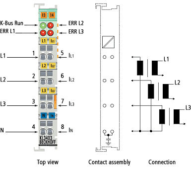 Fig.1: Contact assignment
Terminal point | No.: | Connection for | Comment |
|---|---|---|---|
L1 | 1 | Phase L1 | Connections for the voltage measurement. (See note under Make sure terminal point N is zeroed or grounded!) |
L2 | 2 | Phase L2 | |
L3 | 3 | Phase L3 | |
N | 4 | Neutral conductor N (internally connected to terminal point IN, | |
IL1 | 5 | Current transformer at L1 | Connections for the current transformers. (See note under Operate the current transformer as intended!) |
IL2 | 6 | Current transformer at L2 | |
IL3 | 7 | Current transformer at L3 | |
IN | 8 | Star point of the current transformers |
*) The KL3403-0026 has no capacitive connection to the grounding contact of the mounting rail!
| |
Make sure terminal point N is zeroed or earthed! If you do not connect the terminal point N with the neutral conductor of your mains supply (e.g. if the KL3403 is used purely for current measurements), terminal point N should be earthed, in order to avoid dangerous overvoltages in the event of a current transformer fault! |
| |
Operate the current transformer as intended! Please note that many manufacturers do not permit their current transformers to be operated in no-load mode! Connect the KL3403 to the secondary windings of the current transformers before using the current transformer! |
UL compliance
Follow the instructions indicated below, in order to comply with the specifications of Underwriters Laboratories.
| ||
 | Intended use The terminals are exclusively intended for application with the UL-listed I/O systems of the series BKxxxx, BCxxxx, BXxxxx, LCxxxx, CXxxxx, KLxxxx, KSxxxx or KMxxxx from Beckhoff. | |
| ||
| cULus verification For the cULus verification, the Beckhoff I/O system only examined for risk of fire or electric shock (in accordance with UL508 and CSA C22.2 No. 142). | |
| ||
| Phase voltage according to UL specifications 300 V max. The maximum phase voltage of 500 V described in the technical data should be limited to 300 V for applications requiring UL approval. | |
| ||
| Current transformer Current measurement inputs with the IDs IL1, IL2, IL3, N may only be connected to isolating current transformers, which limit the available current to max. 5 A, 20 V. | |
| ||
| No extended temperature range The limited temperature range applies, if the KL3403-0000 / KS3403-0000 are used according to UL conditions (see Technical data). | |