Settings - Commissioning
Commissioning tab for parametrization the stepper motor control via the KL2531/2541.
 WARNING
The stepper motor can be controlled manually via this dialog mask.
Ensure that your system state permits manual startup of the stepper motor and that hazards for persons or machinery have been ruled out!
The Commissioning tab is only available in path control mode.
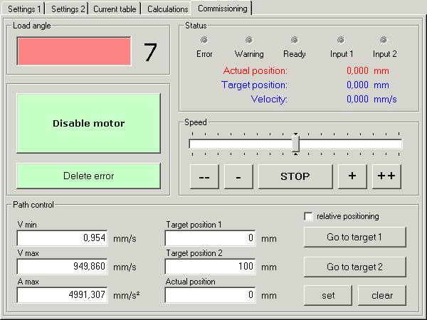
Load angle
The load angle provides information about the current mechanical load at the motor axis.
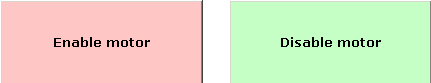
Activate / deactivate motor
This button sets or deletes the enable bit CB.0, thereby enabling or disabling the motor.
Clear Error
If an error has occurred, the button turns red. The error can be cancelled by pressing this button.

Status / position
The actual position is directly coupled with the process input data DataIN. The set position shows the current or last target position of the path control. The velocity is directly coupled with the process output data DataOUT. The value is calculated precisely in mm or mm/s via the application parameters in the Calculations tab. These values have to be specified carefully in order to ensure meaningful operation of the commissioning tool!
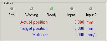
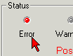
- Error
Status bit SB.6 is shown here. In the event of a fault, clicking on the fault indicator causes a message window to appear that contains plain text information about the error(s).
-
Warning
Status bit SB.5 is shown here.
-
Ready
Status bit SB.0 is shown here.
Speed
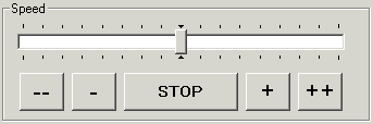
Via the slider you can make the motor rotate counterclockwise or clockwise. The speed increases continuously, the further the slider is moved away from the central position.
The motor can be stopped with the STOP button. The slider will then return to the central position.
The motor can be controlled manually via the --, -, + and ++ buttons. The motor rotates as long as you press and hold the button:
- - | Slow counterclockwise rotation (the speed is increased every 3 seconds as long as the button is pressed) |
- | Very slow counterclockwise rotation |
STOP | The velocity is set to zero, and any active motion command is stopped |
+ | Very slow clockwise rotation |
++ | Slow clockwise rotation (the speed is increased every 3 seconds as long as the button is pressed) |
Path control
The application parameters in the Calculations tab are used for exact calculation in mm, mm/s or mm/s2. These values have to be specified carefully in order to ensure meaningful operation of the commissioning tool!
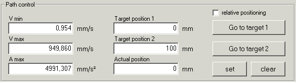
- Vmin minimum velocity (R38)
Here you can specify the minimum value for the velocity.
This value can be changed during operation and is entered in the RAM of the terminal.
- Vmax maximum velocity (R39)
Here you can specify the maximum value for the velocity. The velocity must not exceed the value specified in the Calculations tab and is therefore limited automatically!
This value can be changed during operation and is entered in the RAM of the terminal.
- Amax - maximum acceleration (R40)
Here you can specify the maximum value for the acceleration.
This value can be changed during operation and is entered in the RAM of the terminal.
-
Target position 1 / Target position 2
Here you can specify values for target positions 1 and 2. Positive or negative values are permitted.
- Actual position
Here you can specify the value for the actual position. Positive or negative values are permitted.
- Relative positioning
- If the Relative positioning checkbox is activated, whenever a motion button is pressed the motor moves from the current position by the distance specified in the associated target position.
- If the Relative positioning checkbox is not enabled, the motor travels directly to these absolute target positions when the Start motion 1 or Start motion 2 is pressed.
WARNINGWith relative positioning you can move the stepper motor repeatedly by the distance entered under target position.
If relative positioning is switched off and the Start motion button is pressed again, the stepper motor will return to its absolute target position!
-
Start motion 1 / Start motion 2
The buttons start target approach 1 or target approach 2. Target positions 1 and 2 are written into registers R2 and R3 of the terminal, and the motion command is started.
-
Set
This button saves the value entered in actual position as the new actual position of the terminal.
-
Delete
This button deletes the current position and the current latch values.