PROFINET configuration
 | Supported EtherCAT devices The ER9320-0022 supports only EtherCAT devices listed in the GSDML file; however, extensions are possible. GSDML supports submodules. Find out whether your PROFINET controller supports submodules; if not, some EtherCAT devices cannot be used. |
The ER9320-0022 is integrated into the PROFINET controller using a GSDML file. The GSDML file contains all the parameterization data required for the operation of the ER9320-0022 on the PROFINET controller. The configuration tool reads this file and provides the data to the user.
The EtherCAT devices that can be operated on the ER9320-0022 are also specified in the GSDML file. Not all EtherCAT devices are supported. Therefore, inform yourself first whether the EtherCAT devices that you wish to use are also supported by the ER9320-0022.
Data in the DAP (Device Access Point)
2 x 2 bytes of data are located in the DAP of the GSDML file:
- ECCycleCounter (2 bytes). This is incremented with each EtherCAT cycle (1 ms), provided the EtherCAT Master is in the "OP" state.
- Status (2 bytes). This indicates individual status information bit by bit. These are occupied as follows:
- Bit 0 "IsSynchron": is set when the ER9320-0022 is operated as a PTP slave or IRT device and is synchronous.
- Bit 1 "IsPTPMaster": is set when the ER9320-0022 is operated as a PTP Master.
- Bit 2 "ECFrameError": is set when a problem is detected at the EtherCAT output. The PROFINET diagnostics or the alarms must be read in order to obtain further information.
Parameters in the DAP
- "Activate PN Fallback Value"
- "Off": EtherCAT data is written to zero.
- "On": A different default value can be used with outputs. With digital outputs, for example, the current output process value can be frozen or set to 0 or 1 in case of a PROFINET communication error.
- "Data Presentation"
- "Intel Format": data is displayed in Intel® format.
- "Motorola Format": data is displayed in Motorola format. In Word variables, for example, the high and low bytes are exchanged.
- "EBus error behaviour"
- "Set IOs to 0": in the event of an EtherCAT error, input data and output data are set to zero.
- "Legacy": input data retain their last state, but are no longer updated; output data can still be set (depending on the position of the EtherCAT device).
Mapping
The ER9320-0022 is typically used in a group with EtherCAT devices that are connected to the EtherCAT output. The EtherCAT devices are a component of the GSDML; the EtherCAT devices are parameterized from the PROFINET controller.
Enter the EtherCAT devices in the hardware configurator in the same order as they are physically connected. If EtherCAT star hubs and/or EtherCAT junctions are used, it is important to know the order in which the other EtherCAT devices were entered in the process image (see EtherCAT Mapping).
| Behavior when starting the ER9320-0022 All EtherCAT devices must be present when starting or resetting the ER9320-0022. This means that all connected EtherCAT devices must be powered up before startup or at the same time so that the ER9320-0022 starts up properly on the PROFINET. A solution can be constructed more flexibly with the CX8093. |
Configuration of the EtherCAT devices
There are 4 types of EtherCAT devices:
- EtherCAT devices without process data
- EtherCAT devices with "simple" process data without parameterization
(as a rule, simple EtherCAT devices with digital inputs or outputs) - EtherCAT devices with "simple" process data with parameters
(as a rule, EtherCAT devices with analog inputs or outputs) - EtherCAT devices with different process data and parameters
(for example incremental encoders)
The rule for all of them is: they must be entered in the configuration.
Grouping digital inputs and outputs (pack terminals)
The digital input and output terminals can also be grouped according to their process data. This option can be used with 2 or 4-channel terminals. To do this a 2 or 4-channel pack terminal (without asterisk) must be appended to the GSDML file. In order to fill the byte, a 2 or 4-channel pack terminal (with asterisk) must be appended next. The terminals must be physically and systematically plugged in one behind the other or logically. The byte limit must not be exceeded.
Example
2-channel pack (without asterisk), after that 3 modules from 2-channel pack terminals (with asterisk) may be appended.
Not permitted:
2-channel pack (without asterisk), then 2 modules from 4-channel pack terminals (with asterisk). This exceeds the byte limit.
EtherCAT devices with different process data mappings
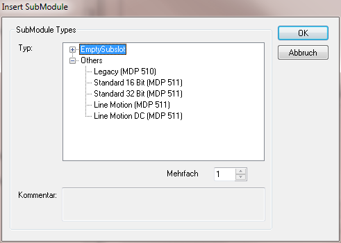
Some EtherCAT devices offer the option to represent different process data ("Predefined PDO Assignments"). In the PROFINET controller, the Predefined PDO Assignments are represented by submodules. The standard mapping is always integrated. If you want to use a process data mapping other than the standard one, delete the standard submodule and insert the desired submodule. It may be that not all mappings can be used under ER9320-0022, contrary to the documentation of the EtherCAT devices.
The following figure shows the insertion of a submodule using the example of an EL5101 EtherCAT Terminal: