Special features of the EP9224
The EP9224 EtherCAT Box offers all the basic properties of the EP9214-0023. Beyond that it permits more detailed settings and a further-reaching diagnosis of the output channels.
The diagnostic information is either directly visible in the process data or can be read out via the logdata.csv log file in the event of an error.
The limitation of the sum current can be implemented as a supplement to the channel current limitation in the EP9214 basic version.
Additional properties
Additional settings in the CoE
Settings for each output channel
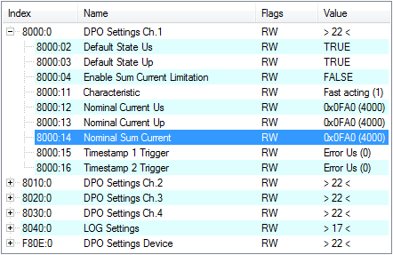
The object 80n0:04 must be enabled in order to activate the sum current limitation.
The sum current can then be defined in the object 80n0:14.
CoE | Title | Description |
|---|---|---|
80n0:04 | Enable Sum Current Limitation | The CoE object 80n0:04 must be set to TRUE in order to activate 80n0:14 |
80n0:14 | Nominal Sum Current | Apart from the nominal current for each Us and Up (basic function of the EP92x4), the sum current of both outputs can also be limited per channel. This property is recommended if the end device may not exceed a total power. The default setting is 4.0 A (4000) and the maximum sum current 8 A. For the EP9224-0037 the default setting is 3.0 A (3000) and the maximum sum current 6 A. The sum current switch-off corresponds to the behavior of the load circuit concerned (CoE 80n0:11). |
80n0:15 / 16 | Timestamp n Trigger | On occurrence of the selected event, the corresponding value (Peak Value n) and the appropriate timestamp are set in the process data. |
If overcurrent (≥ nominal current) is detected and it is foreseeable that the current monitoring will trip if conditions remain unchanged, then a warning is given both in the process data and in form of a flashing LED. An output switch-off due to overcurrent is indicated by a red LED.
If one of the outputs was switched off due to a diagnosis, it must be reactivated by an active RESET.
 | Restart after Power OFF/ON If an output was switched off due to an error, then an active reset by the RESET contact (if existent) or the fieldbus is necessary. Switching off and on again is not sufficient! |
Switch-on can take place either by EtherCAT or by 24 V on the RESET contact (if existent). To protect the circuitry, a RESET can take place maximally every 20 seconds. Faster successive edges are ignored.