The process image is automatically adapted to the selected I/O functions. It always contains exactly those process data objects that are required for the evaluation or control of these I/O functions.
The procedure for selecting the I/O functions is described in the chapter Selection of I/O functions.
For multi-channel I/O functions, the following figures show the process data objects for channel 1 as an example. The process data objects for the other channels have the same content.
ENC Inputs
Depending on the ModuleGroup selected, only a subset of the input data shown below is available in the process data.
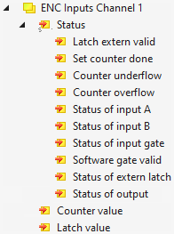
| Latch extern valid
The counter value was saved via the latch input.
(only for “ENC_L_G”) Set counter done
Confirms that the counter value has been set via ENC Outputs > Set counter. Counter underflow
Lower counter limit undershot. The bit is reset when the counter value has fallen below 2/3 of the counting range. Counter overflow
Upper counter limit exceeded. The bit is reset when the counter value has exceeded 1/3 of the counting range. Status of input A - When configured as a counter: Current logic level at input "CNT Clk".
- When configured as an encoder input: Current logic level at input "A".
Status of input B - When configured as a counter: Current logic level at input "CNT Dir".
- When configured as an encoder input: Current logic level at input "B".
Status of input gate
Current logic level of the gate input. Software gate valid
Indicates that the counter has been locked via ENC Outputs Channel n" > "Set software gate". Status of extern latch
Current logic level of the latch input.
(only for "ENC_L_G") Status of output
Current logic level of the threshold output.
(only for "CNT_OUT_DO" and "ENC_OUT_DO") Counter value
Current counter value. Latch value
Latch value.
(only for "ENC_L_G") |
ENC Outputs
Depending on the ModuleGroup selected, only a subset of the input data shown below is available in the process data.
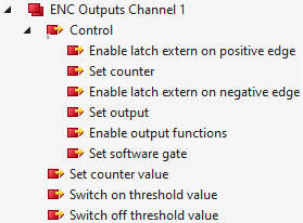
| Enable latch extern on positive edge
Enables saving of the counter value via the latch input with positive edge. Set counter
A positive edge sets the counter value to the value set in "Set counter value". To confirm, the status bit "Set counter done" goes to 1. Enable latch extern on negative edge
Enables saving of the counter value via the latch input with negative edge. Set output
Controls the threshold output if "Enable output functions" = 0.
Is ignored if "Enable output functions" = 1. Enable output functions
Enables the automatic switching of the threshold output at the counter values "Switch on threshold value" and "Switch off threshold value". Set software gate
Locks the current counter value.
To confirm, the status bit "Software gate valid" is set to 1. Set counter value
Counter value default for "Set counter". Switch on threshold value
If the counter value exceeds this value, the threshold output is switched on.
Prerequisite: "Enable output functions" is 1. Switch off threshold value
If the counter value exceeds this value, the threshold output is switched off.
Prerequisite: "Enable output functions" is 1. |