Process image "PLC control"
In the following sections, the letter n serves as a placeholder for the channel number.
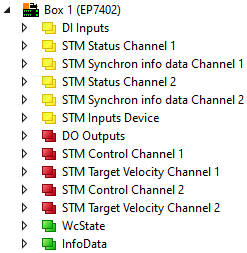
Screenshots showing process data objects of channel 1 are used as examples for both channels. The process data objects of channel 1 and channel 2 have the same content structure.
DI Inputs
| The input variables map the logic level of the digital inputs/outputs in the process data. Make sure that the corresponding output variable in the "DO Outputs" process data object is set to 0 if you want to use a digital input/output as an input. The different designations "Input x" and "Control input x" are only relevant in ZPA mode. In operation without ZPA all digital inputs are equivalent. |
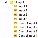
STM Status Channel n
| The input variables "Status" contain the status bits of the motor channels. Ready to enable
Ready
Warning
Error
Moving positive
Moving negative
TxPDO Toggle This bit is inverted each time the status bit is updated. |
STM Synchron info data Channel n
| The input variables “Info data x” contain measured values. You can choose which measured values are mapped to these variables in the CoE directory:
|

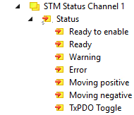
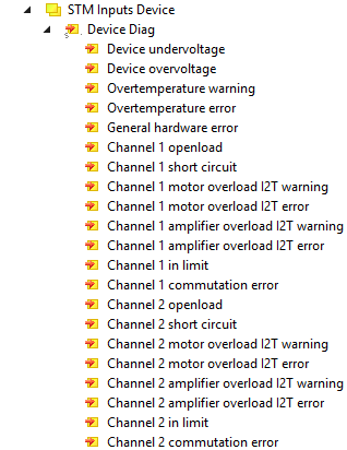
STM Inputs Device
| "STM Inputs Device" contains diagnostic bits that you can use to narrow down the cause of a warning or an error. See chapter Diagnosis bits. |
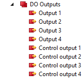
DO Outputs
| Output variables for the digital inputs/outputs. The different designations "Output x" and "Control output x" are only relevant in ZPA mode. In operation without ZPA, all eight digital outputs are equivalent. |
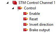
STM Control Channel n
| Enable This bit enables the motor channel. The bit has no effect if the variable Ready to enable is FALSE. Reset Apply a rising signal edge to this bit to acknowledge an error. Invert direction If this bit is set, the setpoint velocity is multiplied by "-1" to change the direction. Brake output (EP7402-0057 only) Output variable for switching the motor brake output. |
STM Target Velocity Channel n
| Velocity Target velocity. Unit: °/s Acceleration This value determines the maximum acceleration. If this value is zero, the acceleration is not limited. Unit: °/s2 Deceleration This value determines the maximum deceleration. A deceleration is not limited if this value is zero. Unit: °/s2 |

 | Save electricity when stationary If the motor is switched on (Enable = 1; Ready = 1) and the motor is not turning (Velocity < Start velocity), it is still energized and held. If the motor is temporarily not needed, set Enable to 0 to save power. Please note that the alignment phase is repeated each time the device is switched back on (Enable = 1). |