Configuration of the main parameters
The data specified here apply to an AS 1050-0120 stepper motor and are intended as an example. For other motors the values may vary, depending on the application.
Setting the CoE objects
 | Execution of changes Changes to CoE objects are only executed after the module has been placed in the Init state. Changes are only active after that. |
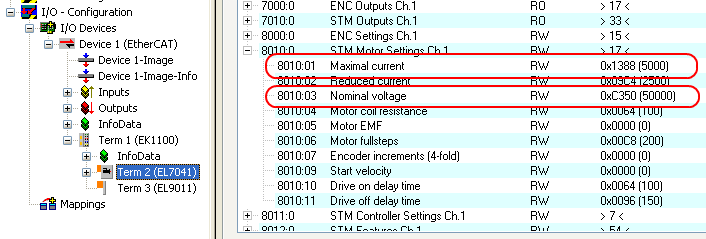
Adaptation of current and voltage
Notice | |
The motor may overheat! In order to prevent overheating of the connected motor it is important to adapt the current and voltage output from the stepper interface to the motor. |
To do this, set the indices 0x8010:01 Maximal current and 0x8010:03 Nominal voltage in the CoE register to suitable values (see Fig. Adaptation of current and voltage).
Reduced current can be set in index 0x8010:02. This reduces the coil current when at a standstill (and therefore the power dissipation). Please note that the torque is also reduced.
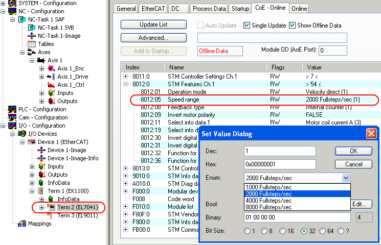
Base frequency selection
Microstepping is set to 1/64 and cannot be changed. However, the base frequency can be changed (default: 2000). To do this, mark the module and select the CoE Online tab. Change the base frequency by double-clicking on the index 0x8012:05 Speed range (Fig. Setting the base frequency).
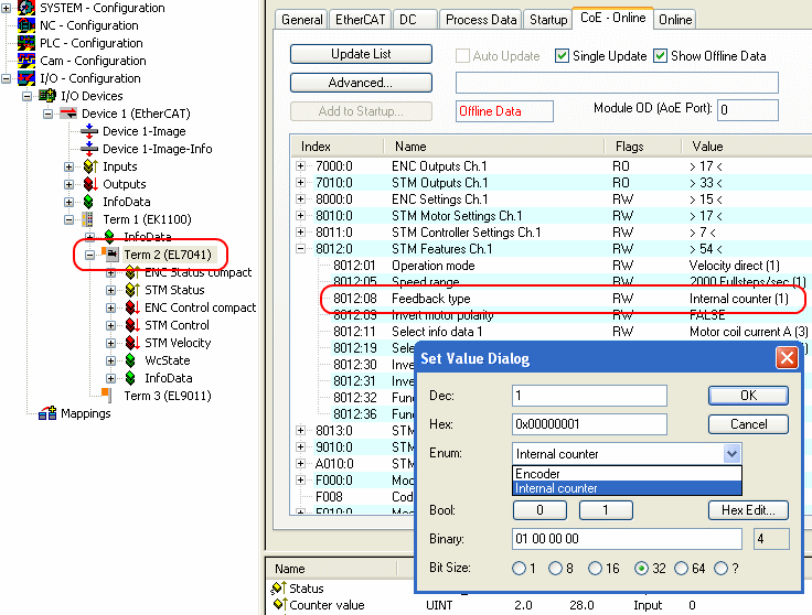
Selecting the feedback system
The module with encoder connections provides a choice of two possibilities for the feedback system:
- Internal Counter (default): Use internal counter for position feedback
- Encoder: Use external encoder for position feedback
| Setting the feedback type By default, the stepper module is set to internal counter. If an external encoder is used, the setting must be changed by double-clicking on the index 0x8012:08 Feedback type in the Enum menu (Fig. Selecting the feedback system). |
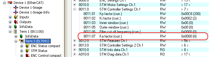
KA factor (EP7041-0002 and EP7041-1002 only)
The KA factor can be used to adapt the current during the acceleration phases. The current increase is calculated as follows.
Current increase in mA = speed difference x KA / 1000
The steeper the speed ramp, the higher the current increase.
This value can be set in index 0x8011:07 Ka factor (curr.) (see fig. Setting the KA factor).
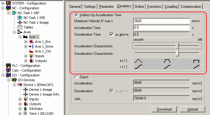
NC settings
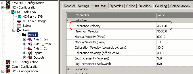
Reference speed selection
The maximum speed can be calculated from the base frequency and the motor frequency.
v max = base frequency / motor frequency = (2000 full steps / s) / (200 full steps / rev) = 10 revolutions / s
The reference speed can be calculated by multiplying the maximum speed with the distance per revolution.
v ref = 10 revolutions / s x 360° = 3600 °/ s
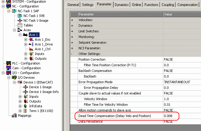
Dead time compensation
The dead time compensation should theoretically be 3 cycles of the NC cycle time, although in practice 4 cycles are preferable. At a cycle time of 2 ms it should therefore be 0.008 s. The dead time compensation can be found under Advanced Settings in the encoder parameters.
Scaling factor
The scaling factor can be changed by selecting NC Axis 1_Enc and the Parameter tab in the NC (see fig. Setting the scaling factor (example with encoder)). The value can be calculated with the formulas specified below.
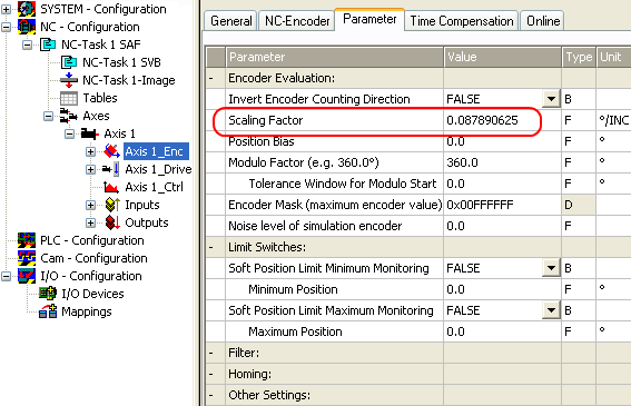
Calculation of the scaling factor
with encoder:
SF = distance per revolution / increments x 4 = 360° / 1024 x 4 = 0.087890625 mm / INC
without encoder:
SF = distance per revolution / full steps x microsteps = 360° / 200 x 64 = 0.028125 mm / INC
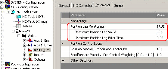
Position lag monitoring
The position lag monitoring function checks whether the current position lag of an axis has exceeded the limit value. The position lag is the difference between the set value (control value) and the actual value reported back. If the terminal parameters are set inadequately, the position lag monitoring function may report an error when the axis is moved. During commissioning it may therefore be advisable to increase the limits of the Position lag monitoring slightly.
Notice | |
ATTENTION: Damage to equipment, machines and peripheral components possible! Setting the position lag monitoring parameters too high may result in damage to equipment, machines and peripheral components. |
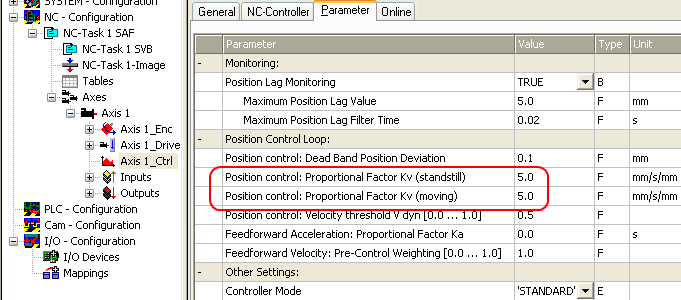
Kv factors (only with external encoder)
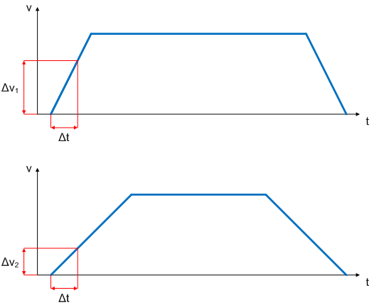
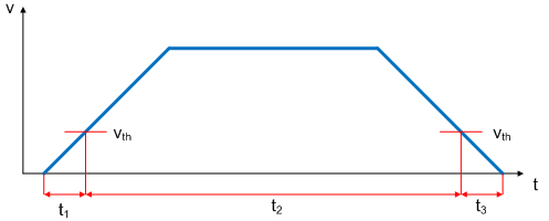
In the NC two proportional factors Kv can be set under Axis 1_Ctrl on the Parameter tab. First select the position controller Type with two P constants (with KA) under the NC Controller tab. The two P constants are for the Standstill range and for the Moving range (see Fig. Setting the proportional factor KV). The factors can be used to set the start-up torque and the braking torque to a different value than the drive torque. The threshold value can be set directly below (Position control: Velocity threshold V dyn) between 0.0 (0%) and 1.0 (100%). Fig. Velocity ramp with KV factor limit values shows a speed ramp with thresholds of 30%. The Kv factor for Standstill (t1 and t3) can be different than the Kv factor for Moving (t2). In this case the same factor was used, since for stepper motors this function is less crucial than for DC motors.
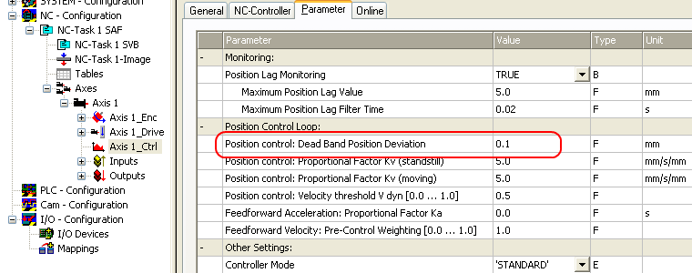
Dead band for position errors
Microstepping can be used to target 200 x 64 = 12800 positions. Since the encoder can only scan 1024 x 4 = 4096 positions, positions between two encoder scan points may not be picked up correctly, in which case the terminal will control around this position. The dead band for position errors is a tolerance range within which the position is regarded as "reached" (Fig. Dead band for position errors).
Setting the acceleration time
In order to pass through any resonances that may occur as quickly as possible, the ramps for the acceleration time and the deceleration time should be as steep as possible.