Process image
The scope of the process image is adjustable. Not all process data objects are enabled in the factory settings. Configure the process image according to your requirements.
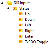
DIS Inputs
"DIS Inputs" contains the input variables of the navigation switch.
| Status
|
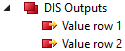
DIS Outputs
"DIS Outputs" contains variables for numerical values that can be shown on the display.
| Value row 1: Variable for the upper row of the display. Value row 2: Variables for the lower row of the display. |
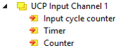
UCP Input Channel n
The "UCP Input Channel n" contain variables for the evaluation of the timer and counter.
These process data objects are disabled in the factory settings. Enable
| Input cycle counter: A 2-bit counter. It is incremented every time the variables "Timer" or "Counter" are updated. Timer: the current value of the timer. Counter: the current value of the counter. |
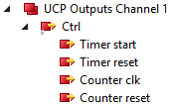
UCP Outputs Channel n
The "UCP Outputs Channel n" contain variables for controlling the timer and counter.
These process data objects are disabled in the factory settings. Enable
| Ctrl
|
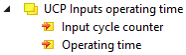
UCP Inputs operating time
"UCP Inputs operation time" contains variables for evaluation the operating hour counter.
This process data object is disabled in the factory settings. Enable
| Input cycle counter: A 2-bit counter. It is incremented every time the variable "Operating time" is updated. Operating time: The counter value of the operating hour counter. Unit: seconds. |