Settings
Table of contents |
|---|
Selection of the analog signal type, index 0xF800:0n
In delivery state, all channels of the EP31xx are set for analog voltage measurement (-10 V …+10 V).
Notice | |
Setting the correct signal type before connecting the sensors Set the correct signal type before connecting the sensors! |
This setting can be made individually for each channel in the CoE object 0xF800:0n. Changes are immediately effective.
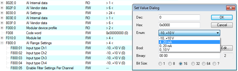 Fig.15: EP31x4-0002: Selection of the signal type
In the case of the EP31x2 the signal type -20 mA to +20 mA can additionally be selected (see illustration below).
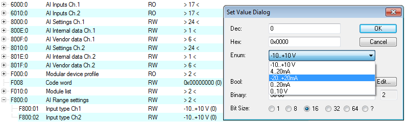 Fig.16: EP31x2: Selection of the signal type
Presentation, index 0x80n0:02
The measured value output is set in factory to two's complement representation (signed integer).
Index 0x80n0:02 offers the possibility to change the method of representation of the measured value.
- Signed integer representation
The negative output value is represented in two’s complement (negated + 1).
Maximum representation range with 16-bit = -32768 .. +32767dec
Input signal | Value | ||||
|---|---|---|---|---|---|
+/- 10 V | 0...20 mA | 4...20 mA | 0...10 V | decimal | hexadecimal |
10 V | 20 mA | 20 mA | 10 V | 32767 | 0x7FFF |
5 V | 10 mA | 12 mA | 5 V | 16383 | 0x3FFF |
0 V | 0 mA | 4 mA | 0 V | 0 | 0x0000 |
-5 V | - | - | - | -16383 | 0xC001 |
-10 V | - | - | - | -32767 | 0x8000 |
Overview of further representations
- Unsigned integer representation
The output value is represented with 15-bit resolution without sign, therefore polarity detection is no longer possible.
Maximum representation range with 16-bit = 0 .. +32767dec
- Absolute value with MSB as sign - representation
The output value is displayed in magnitude-sign format: MSB=1 (highest bit) in the case of negative values.
Maximum representation range with 16-bit = -32768 .. +32767dec
Input values (+/- 10 V) | Representation (values dec. / values hex.) | |
|---|---|---|
unsigned integer | Absolute value with MSB as sign | |
10 | 32767 / 0x7FFF | 32767 / 0x7FFF |
5 V | 16383 / 0x3FFF | 16383 / 0x3FFF |
0 V | 0 / 0x0000 | 0 / 0x0000 |
-5 | 16384 / 0x4000 | [-16384] / 0xC000 |
-10 | 32767 / 0x7FFF | [-32767] / 0xFFFF |
 | Presentation types The presentation types Unsigned integer and Absolute value with MSB as sign have no function for unipolar modules. There is no change in the presentation in the positive range. |
Siemens bits, index 0x80n0:05
If this bit is set, status displays are superimposed on the lowest three bits. In the error case "overrange" or "underrange", bit 0 is set.
Underrange and overrange, index 0x60n00:01, 0x60n00:02
Underrange and overrange is indicated as follows:
- The bits "Underrange", "Overrange" and "Error" in the process data are set.
- The "Error" LED of the affected channel lights up red.
The threshold values for the mentioned bits and the LED can be found in chapter Measuring ranges.
Limit 1 ad Limit 2, index 0x80n0:13, index 0x80n0:14
If the limits of the values that can be entered in indices 0x80n0:13 and 0x80n0:14 are violated, the bits in indices 0x60n0:03 and 0x60n0:05 are set accordingly (see sample below). The indices 0x80n0:07 or 0x80n0:08 serve to activate the limit value monitoring.
Output limit n (2-bit):
- 0: not active
- 1: Value < limit value
- 2: Value > limit value
- 3: Value = limit value
| Limit evaluation The limit evaluation assumes a signed representation. The conversion to the desired representation (index 0x80n0:02) only takes place after the limit evaluation. |
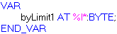
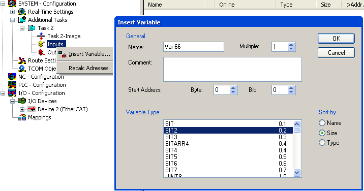
| Linking in the PLC with 2-bit values
|
Sample
Channel 1; Limit 1 and Limit 2 enabled, Limit 1 = 2.8 V, Limit 2 = 7.4 V, representation: signed integer
Entry in index (Limit 1): 0x8000:13
(2.8 V / 10 V) x 216 / 2 - 1 = 9,174dec
Entry in index (Limit 2): 0x8000:14
(7.4 V / 10 V) x 216 / 2 - 1 = 24,247dec
Output:
Input channel 1 | Index 0x6000:03 | Index 60x6000:05 |
|---|---|---|
1.8 V | 0x01hex, (Limit 1, limit value undershot) | 0x01hex, (Limit 2, limit value undershot) |
2.8 V | 0x03hex, (Limit 1, limit value reached) | 0x01hex, (Limit 2, limit value undershot) |
4.2 V | 0x02hex, (Limit 1, limit value exceeded) | 0x01hex, (Limit 2, limit value undershot) |
8.5 V | 0x02hex, (Limit 1, limit value exceeded) | 0x02hex, (Limit 2, limit value exceeded) |
Swap Limit index 0x80n0:0E
The limit function can be inverted by SwapLimitBits in index 0x80n0:0E.
Output Limit n (2-bit):
SwapLimitBits setting | Value |
|---|---|
FALSE (default setting) |
|
TRUE |
|
The Swap Limit function is available according to the table below
EtherCAT Box | Swap Limit function from rev. |
|---|---|
EP3162-0002 | -0016 |
EP3174-0002 | -0018 |
EP3174-0092 | -0016 |
EP3182-1002 | -0017 |
EP3184-0002 | -0017 |
EP3184-1002 | -0018 |