EL9148, EL9188, EL9189 - Introduction and technical data
 Fig.26: EL9184
 Fig.27: EL9188, EL9189
The EL9188 and EL9189 potential distribution terminals provide 16 terminal points with a potential and enable the tapping of voltage without further bus terminal blocks or wiring.
The EL9184 provides the potential of the 24 V DC contact at eight terminal points and the potential of the 0 V contact at eight terminal points.
Single-wire conductors can be connected without tools using the direct plug-in technique.
The HD EtherCAT Terminals (High Density) with increased packing density are equipped with 16 connection points in the housing of a 12-mm terminal block.
Technical data
Technical data | EL9184 | EL9188 | EL9189 |
|---|---|---|---|
Nominal voltage | ≤ 60 VDC | ||
Current load | ≤ 10 A | ||
Power LED | - | ||
Defect LED | - | ||
Message to E-bus | - | ||
Shield connection | - | ||
Renewed infeed | - | ||
Connection facility to additional power contact | 8 | 16 | |
Side by side mounting on EtherCAT Terminals with power contact | yes, left without power contact ground | ||
Side by side mounting on EtherCAT Terminals without power contact | - | ||
Outputs | 2 x 8 | 16 | 16 |
E-bus current consumption | - | ||
Bit width in process image | 0 | ||
Electrical connection to mounting rail | - | ||
Electrical isolation | 500 V (E-bus/field voltage) | ||
Dimensions (W x H x D) | approx. 15 mm x 100 mm x 70 mm (width aligned: 12 mm) | ||
Configuration | no address or configuration settings required | ||
Conductor types | solid wire, stranded wire and ferrule | ||
Conductor connection | solid wire conductors: direct plug-in technique; | ||
Rated cross-section | solid wire: 0.08 ... 1.5 mm²; | ||
Weight | approx. 60 g | ||
Permissible ambient temperature range during operation | -25°C ... +60°C | ||
Permissible ambient temperature range during storage | -40°C ... +85°C | ||
Permissible relative air humidity | 95 %, no condensation | ||
on 35 mm mounting rail, conforms to EN 60715 | |||
Enhanced mechanical load capacity | yes, see Installation instructions for terminals with enhanced mechanical load capacity | ||
Vibration / shock resistance | conforms to EN 60068-2-6 / EN 60068-2-27 | ||
EMC immunity / emission | conforms to EN 61000-6-2 / EN 61000-6-4 | ||
Protection rating | IP20 | ||
Installation position | variable, see chapter Mounting of passive terminals | ||
Approvals / markings* | |||
*) Real applicable approvals/markings see type plate on the side (product marking).
Ex markings
Standard | Marking |
|---|---|
ATEX | II 3 G Ex ec IIC T4 Gc |
IECEx | Ex ec IIC T4 Gc |
EL9184 connection
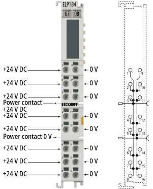 Fig.28: EL9184 connection
Terminal point | Description | |
|---|---|---|
Name | No. | |
+24 V | 1 - 8 | +24 V output (connected to positive power contact) |
0 V | 9 - 16 | 0 V output (connected to negative power contact) |
EL9188 connection
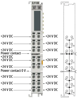 Fig.29: EL9188 connection
Terminal point | Description | |
|---|---|---|
Name | No. | |
+24 V | 1 - 16 | +24 V output (connected to positive power contact) |
EL9189 connection
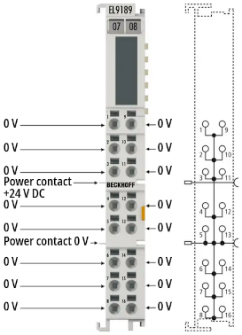 Fig.30: EL9189 connection
Terminal point | Description | |
|---|---|---|
Name | No. | |
0 V | 1 - 16 | 0 V output (connected to negative power contact) |