Power supply as EtherCAT device
The terminal is set ready for operation ex factory with default settings for the 20 V output and FloatingPoint PDO (Real32). Experienced users can put the channel into operation by
- scanning the terminal in TwinCAT (or adding it manually in the configuration, paying attention to the EtherCAT revision!),
- reloading in TwinCAT,
and outputting a value via OnlineWrite/OnlineForce or linked to the PLC:
 Fig.148: Output of 4.256 V
To gain a deeper understanding of the capabilities of this product, it is recommended that you read the following sections.
Recommended commissioning procedure
After the configuration has been created, the terminal supplies numerical values as REAL32-PDO (PDO = process data object) as the default process image:
AO: PDO concerning the analog output
- Status (yellow) + output data (red)
AI: PDO concerning the feedback measurements
- Output voltage
- Output current
- Set TwinCAT in Config/FreeRun, the terminal goes into the OP state -> deliver State=8 and WcState=0, see Fig. below
- If the terminal already has a usage history, a CoE reset can be used to undo previous parameter changes that were saved in the terminal: to do this, enter 0x64616F6C in object 0x1011:01.
- A load can be connected for testing without PLC programming and a voltage can be output:
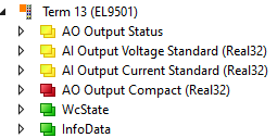 Fig.149: TwinCAT tree EL9501
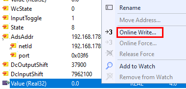 Fig.150: Right-click on PDO Value (Real32) -> Online Write
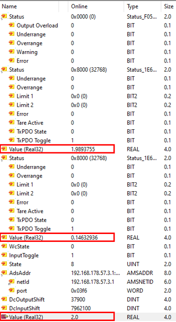 Fig.151: Sample output of values
Example output of nom. 2.0 V, back-measured 1.98 V at 146 mA current, i.e. 13.7 Ω load (note the measurement uncertainty specifications in the chapter "Technical data", this power supply terminal is not a precision measuring device!)
Parameterization
Depending on the application requirements, the basic PDO setup of the Predefined PDO must be chosen:
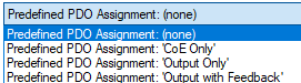 Fig.152: Predefined PDO
- CoE only: Operation without process data (see chapter "Power supply stand-alone"), the terminal is controlled via CoE settings
- Output only: Operation only with output PDO, corresponding CoE settings are overridden by the PDO
- Output with feedback: Real-time output PDO and feedback measurements, corresponding CoE settings are overridden by the PDO
This power supply terminal is always controlled by CoE parameters unless it is overridden by an activated/mapped PDO (not overwritten, i.e. the CoE value remains untouched). The following table shows the relationship between PDO and CoE (as background for the following commissioning steps):
| PDO | CoE |
|---|---|---|
AO Output | x1600: AO Output Standard (INT16).Control.Output Interface (0x7000:15) | Output Interface (0x800D:11) |
x1600: AO Output Standard (INT16).Control.Output Operation (0x7000:16) | PowerOn Output Operation (0x800D:23) | |
x1600: AO Output Standard (INT16).Value (0x7000:11) | PowerOn Output Value (0x800D:24) | |
x1601: AO Output Compact (INT16).Value (0x7000:11) | ||
|
| |
x1602: AO Output Standard (Real32).Control.Output Interface (0x7000:15) | Output Interface (0x800D:11) | |
x1602: AO Output Standard (Real32).Control.Output Operation (0x7000:16) | PowerOn Output Operation (0x800D:23) | |
x1602: AO Output Standard (Real32).Value (Real32) (0x7000:13) | PowerOn Output Value (0x800D:24) | |
x1603: AO Output Compact (Real32).Value (Real32) (0x7000:13) | ||
|
| |
Current limitation | x1610: AO Complementary Limit High Standard (INT16) Value (0x7010:11) | PowerOn Output Value (0x801D:24) |
x1612: AO Complementary Limit High Standard (Real32) Value (Real32) (0x7010:13) |
The 5 (EL9501) or 4 (EL9561) channels of the terminal must be parameterized in sequence as follows:
Parameterization of the output voltage AO Output
- The following process data (PDO) are available
- Standard (Real32) (default): status + output value in FloatingPoint/Real32
- Compact (Real32): only output value in FloatingPoint/Real32
- Standard (INT16): status + output value in Integer (INT16)
- Compact (INT16): only output value in Integer (INT16)
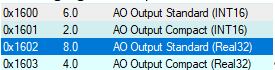 Fig.153: AO Output PDOs
In PDO and CoE, the channel basically behaves like an analog output described in the chapter "Analog output commissioning" with the functions described there
Parameters for this in CoE x8000..x800F, in particular can be changed as required:
- Output range x800D:11
- The levels of "Warning" at x800D:15/16 and "Limiter" x800D:1C/1D
The limiter acts as an output limiter. - The "SlewRate" in x800D:1E: the SlewRate setting limits the maximum electrical rate of change, e.g. to prevent a connected load from being loaded with excessively steep edges. "0 sec" corresponds to "no limit"
- Process data representation x800D:12: only LegacyRange is available, for operation with INT16 PDO
- Informative: info data in CoE x9000...x900F
 Fig.154: Output range x800D:11
Two properties that are actually controlled via CoE can also be controlled via PDO, for example in a very dynamic application with rapidly changing operating states. In such cases, an attribute change via ADS CoE command would take too long.
- x800D:11 Output Interface:
- None = 0dec (deactivation of the output with deletion of the settings)
- 5 V = 13dec (warning and limiter are set to corresponding default)
- 20 V = 15dec (warning and limiter are set to corresponding default)
- x800D:23 PowerOnOperation:
- Line On = 0dec
- Line Off = 1dec
Note: The electrical effect of "Line Off" is the same as with an output setpoint of 0 V and "Line On". Line Off is useful if the terminal output is to be shutdown even though the output setpoint from the controller is supplied continuously via PDO/EtherCAT and is >0.
To do this, x1600 or x1602 must be mapped/activated from the PDO list:
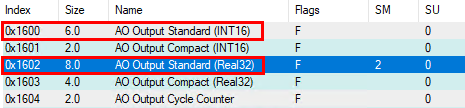 Fig.155: Activate PDOx1600 and x1602
The linkable control appears as a PDO, e.g:
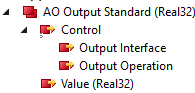 Fig.156: Control PDO
These are each to be filled as WORD/INT16 with the above values.
Note in the introductory text! The corresponding CoE value does not change! For example, if the interface is switched to 5 V via PDO, "20 V" remains visible in the CoE x800D:11.
Watchdog behavior (output behavior in the event of a communication interruption)
The watchdog works with parameters in 0x8000:05 and :13/14 (for INT16 PDO) and x800D:1A/1B (for Real32 PDO), as described in the basic chapter "Analog output commissioning"
The following setting is useful for most power supplies:
 Fig.157: Watchdog setting
PowerOn Output Operation
It can be particularly useful for a power supply to provide an output before the controller or EtherCAT has started up. This is parameterized in CoE x800D:23/24.
 Fig.158: Power Output Operation PDO
Example: Output of 4.2 V immediately when the terminal is powered on
As soon as the terminal is powered up under EtherCAT (OP state), it adopts the PDO setpoint.
The watchdog must be set to "Last output Value" for this purpose
Fig.157: Watchdog settingExample: The output voltage is 4.2 V, as soon as power is applied to the terminal and EtherCAT has set the terminal to OP (WcState = 0), 3.0 V is specified by the PLC (green: feedback measurement with ELM3102-0100).
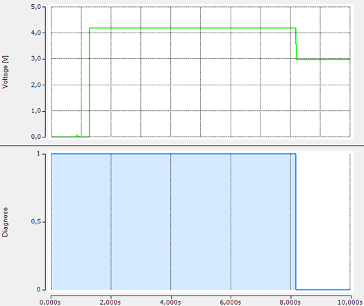 Fig.160: Output voltage diagram
Parameterization of the output current
(AO Complementary, i.e. current limitation of the output)
- Explanation of the term "complementary" see Introduction
- The current limitation is technically always active, there is a warning and a limit function
- In PDO and CoE, the channel basically behaves like an analog output described in the chapter "Commissioning analog output" with the functions described there
Parameters for this in CoE x8010..x801F, in particular can be changed as required:
- "Warning Level High" x801D:16 (default 2 A)
- "Limiter High Value" x801D:1D (default 2 A)
- Informative: info data in CoE x9010...x901F
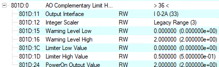 Fig.161: 801D PDO
The behavior in the event of overcurrent is set in CoE x800D:29:
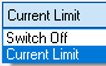 Fig.162: Overcurrent behavior
- Current Limit (default): The output voltage is automatically reduced if necessary.
- Switch Off: In the event of an overload, the terminal goes into "Error". The output voltage remains 0 V until the output setpoint has been reset to 0 V once. The error state is terminated and normal operation is then possible.
Output Overload Acceptance Time in x800D:26
- Time specification of how long the terminal suppresses an overload message via PDO AO Output Status
- This is to prevent the error message from being issued in the event of a brief overcurrent, for example in the event of high starting currents.
- There is always an electrical current limitation
- Default: 50 ms
Example: OverloadAcceptanceTime = 500 ms, the output voltage (green) collapses in the event of a short circuit, only 500 ms later is this reported via bit PDO AO Output Status.Output Overload.
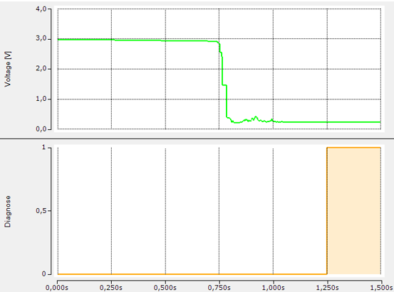 Fig.163: Example OverloadAcceptanceTime
There are two conceivable uses for the AO Complementary:
- The current limitation is fixed in the CoE as above and, if necessary, changed via ADS CoE at operating time.
The current limitation value is in PowerOn Output Value (0x801D:24). - A PDO can be activated and linked to the controller that allows very dynamic control of the current limitation. In fact, the terminal can be operated in CC (constant current) current supply mode (taking into account the uncertainties, see Technical data) if a (too) high output voltage is specified at the same time and the terminal is constantly running in current limitation mode.
The current supply value is then evaluated with regard to warning and limiter, see chapter "Commissioning analog output
The following optional process data (PDO) is available for this purpose: - x1A10 AO Complementary Limit High Status for diagnosis
- x1612 or x1610 AO Complementary Limit High Standard for setpoint specification, which overruns the PowerOn Output Value (0x801D:24) according to the table.
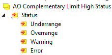 Fig.164: x1A10 AO Complementary Limit High Status
 Fig.165: x1612 or x1610 AO Complementary Limit High Standard
Example of an application-specific current limitation:
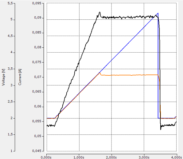 Fig.166: Example diagram for an application-specific current limitation
Blue: Output ramp 2...5.2 V at 57 Ω, current limitation in x801D:1D to 0.1 A (for measurement uncertainty of current feedback measurement, see Technical data!)
Black: Current flow as shown
Orange: back-measured output voltage, which is limited to approx. 3.3 V.
Parameterization of the feedback measurement of the output voltage, AI Output Voltage
The following process data (PDO) are available:
- Standard (Real32) (default): status + measured value in FloatingPoint/Real32
- Compact (Real32): only measured value in FloatingPoint/Real32
- Standard (INT16): status + measured value in Integer (INT16, note MBE!)
- Compact (INT16): only measured value in Integer (INT16, note MBE!)
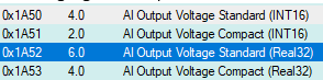 Fig.167: 1A50 PDO
In PDO and CoE, the channel basically behaves like an analog input described in the chapter "Analog input commissioning" with the functions described there.
- Parameters for this in CoE x8050..x805F
- In particular, the measuring range 0...5/20 V is changeable (x805D:11)
- Informative: info data in CoE x9050...x905F
Parameterization of the feedback measurement of the output current, AI Output Current
Only as measuring range 0...2 A
The following process data (PDO) are available:
- Standard (Real32) (default): status + measured value in FloatingPoint/Real32
- Compact (Real32): only measured value in FloatingPoint/Real32
- Standard (INT16): status + measured value in Integer (INT16, note MBE!)
- Compact (INT16): only measured value in Integer (INT16, note MBE!)
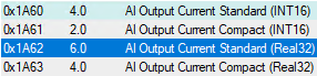 Fig.168: 1A60 PDO
In PDO and CoE, the channel basically behaves like an analog input described in the chapter "Analog input commissioning" with the functions described there.
- Parameters for this in CoE x8060..x806F
- -Informative: info data in CoE x9060..x906F
Parameterization of the measurement of the input voltage, AI Input Voltage
Only selectable with EL9501, only as measuring range 0...30 V
The following process data (PDO) are available:
- Standard (Real32): status + measured value in FloatingPoint/Real32
- Compact (Real32): only measured value in FloatingPoint/Real32
- Standard (INT16): status + measured value in Integer (INT16, note MBE!)
- Compact (INT16): only measured value in Integer (INT16, note MBE!)
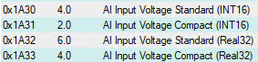 Fig.169: 1A30 PDO
In PDO and CoE, the channel basically behaves like an analog input described in the chapter "Analog input commissioning" with the functions described there.
- Parameters for this in CoE x8030..x803F
- Informative: info data in CoE x9030...x903F
The device information can be read out in the CoE
- CoE range F900 (see chapter "Device information")
- LED status (see chapter "LED status")
The terminal is now ready for operation.