Operating notes
The EL95x1 is a 24V-to-x power supply in 12 mm terminal format that can be controlled via EtherCAT.
Interface topology
The EL95x1 has two analog outputs (from the point of view of the EtherCAT controller or PLC/TwinCAT), namely the voltage setpoint and the current limitation. It also has two or three analog inputs for feedback measuring the current device status:
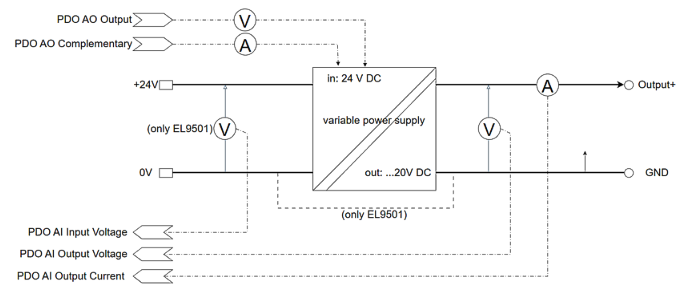 Fig.138: Presentation EL9501
The analog channels are structured and adjustable in the configurative representation (TwinCAT configuration) = PDO and CoE (parameters) like normal analog inputs and outputs of the Exxx7x device class (e.g. EL307x, ED407x etc.).
Use of the terminal
- as a power supply that can be accessed/parameterized online via EtherCAT,
- controlled via cyclic PDOs, preferably for dynamic operation
- controlled via CoE: deactivate PDO mapping, parameters are then accessible via ADS. Preferred for static operation and to save process data on the EtherCAT bus
- as a standalone power supply without EtherCAT and coupler
- The terminal can only be parameterized via EtherCAT, so the parameters, as well as the desired output voltage, must be stored once in the device (CoE) via EtherCAT. The settings are saved. The terminal then outputs the set voltage after the PowerOn, even without EtherCAT (coupler). It operates permanently in the watchdog state. However, diagnostics are then not possible.
The EL9501 or EL9561 is supplied with the supply voltage nom. 24 V DC for the voltage output via the power contacts from the left or directly via terminals 2/6 and 3/7. Sufficient load capacity of the voltage source must be ensured here.
The terminal is designed for operation in the assumed nominal output range of 5 or 20 V. It is also technically output-capable (see technical data "Technical output range"), although the limit depends on the hardware. This range can be used following a case-by-case assessment. However, in a series application or if interchangeability is required, only the "Nominal output range" should be used.
Sample output EL9561
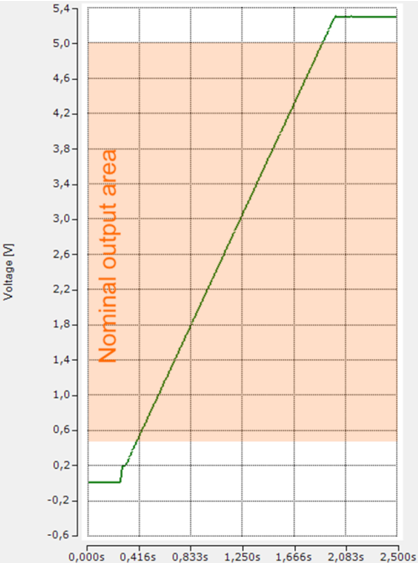 Fig.139: Example diagram of ramp output with PDO setpoint specification
Example: ramp output with PDO setpoint specification 0...6 V in output range 5 V, resulting in measured real value output 0.25 to 5.29 V, indication of the internal voltage measurement.
If the setpoint specification is below the nominal output range, the real value output only starts from the minimum nominal output value:
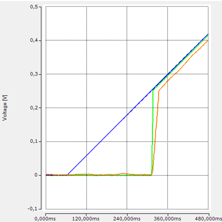 Fig.140: Example diagram setpoint specification, feedback measurement
Legend:
blue: (ideal) PLC setpoint specification,
orange: internal "AI Output Voltage" feedback measurement, attenuated by 50 Hz IIR filter,
green: external feedback measurement, slightly attenuated by 1000 Hz FIR filter
Parallel/series connection
It is permissible to connect several EL95x1 in parallel to increase the current.
However, the usability must be checked in the respective application, as resonance or fluctuation effects can occur due to the arbitrary complexity or impedance.
It is permissible to connect several EL9561 in series to increase the voltage or to simulate cascaded voltages. The specified insulating strength according to the Technical data must be observed!
Current limitation
Since resonance or fluctuation effects may occur due to the arbitrary complexity/impedance, the usability must be checked in the respective application.
The output channel can be provided with a parameterizable current limitation called "AO Complementary Limit High". The term "complementary" refers to the fact that the AO channel works as a CV (voltage output). Ohmic is the current resulting from the load that is to be limited (see corresponding description in chapter Commissioning).
Overcurrent events are only recognized as such from a duration of approx. 3 ms.
Analog output channels
The terminal works internally with 5 analog channels and corresponding CoE ranges, which can be seen in the CoE or the variable overview:
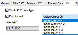 Fig.141: CoE overview, analog channels
- Analog Output Ch.1: voltage output
CoE: Parameter in x8000 - x800F, InfoData in x9000 - x900F - Analog Output Ch.2: current limitation "Complementary High"
CoE: parameter in x8010 - x801F, InfoData in x9010 - x901F - Analog Input Ch.1: measured input voltage (EL9501 only)
CoE: Parameter in x8030 - x803F, InfoData in x9030 - x903F - (Analog Input Ch.2: internal measuring channel, not accessible)
- Analog Input Ch.3: measured output voltage
CoE: Parameter in x8050 - x805F, InfoData in x9050 - x905F - Analog Input Ch.4: measured output current
CoE: Parameter in x8060 - x806F, InfoData in x9060 - x906F
Output characteristic diagram
The output characteristic diagram results from the specified max. power:
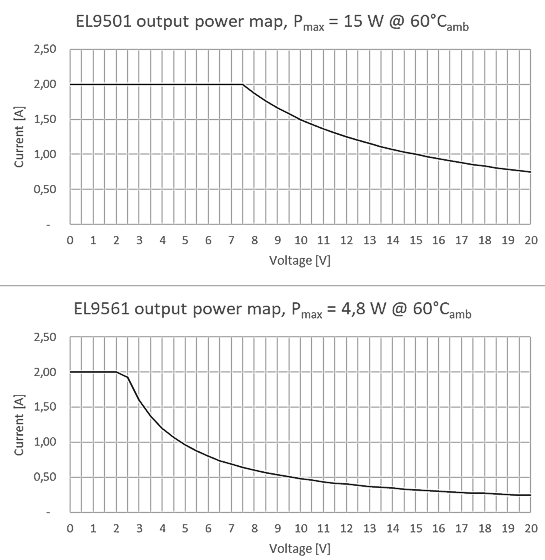 Fig.142: Output characteristic diagram EL9501, EL9561
A higher output power at lower temperatures or with the use of a fan is not possible due to the current-limiting internal components.
If there is a load due to a voltage drop on the line, the scaler in the AO output can be set to >1, for example, to achieve an excessive voltage output compared to the PLC setpoint.