Commissioning and parameterization of the EL922x with EtherCAT
To commission the EL922x with EtherCAT, proceed as follows:
- Mounting
Mount the EL922x as described in the chapter Mounting and wiring - Terminal wiring
Power supply
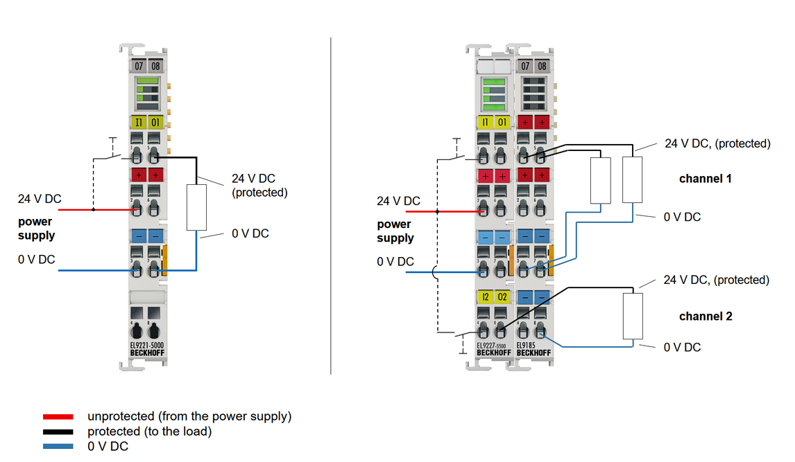
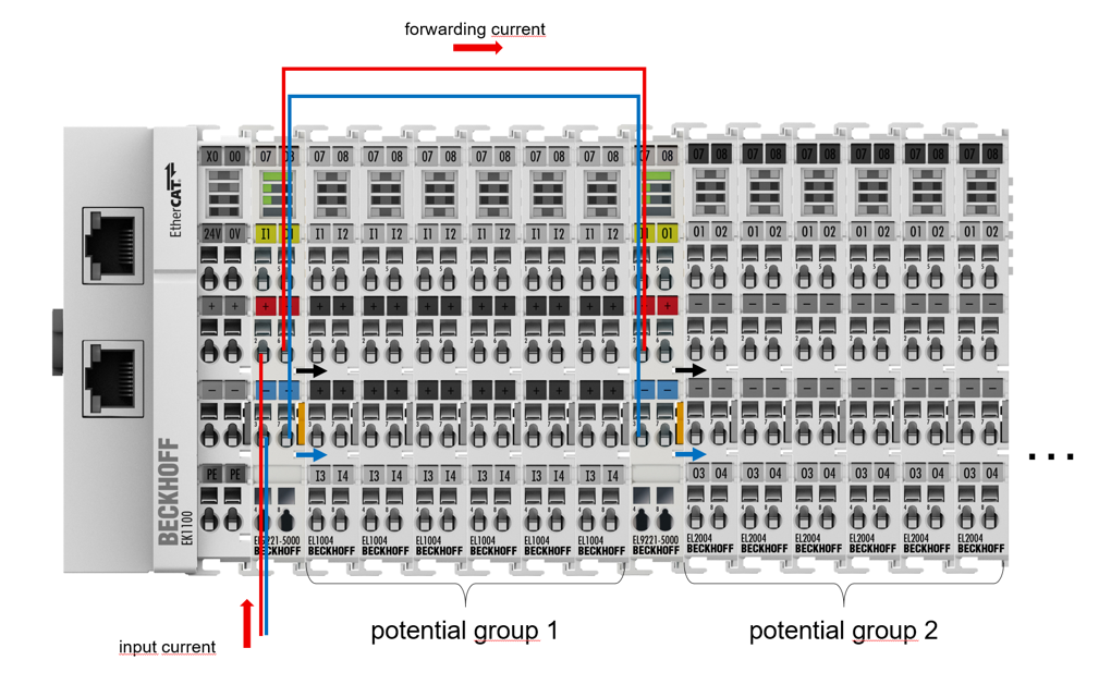
Connect the 24 V DC power supply to the respective terminal contacts. Supply 24 V DC to terminal contacts 2 or 6 and 0 V to terminal contacts 3 or 7. The maximum permissible input current, in case of forwarding the input voltage, can be found in the technical data.
(Input current = forwarding current + current of the own terminal)
Protected output
Connect output 1 to terminal point 5 and/or use the power contact. Output 2 is tapped via terminal point 8 (no further power contact is available here)
Digital inputs
Connect the digital inputs (for switching and resetting the outputs) to terminal point 1 for switching output 1 and terminal point 4 for switching output 2. A negative edge of 24 V DC is required. NOTICE
- Configuration
Create a configuration in the TwinCAT System Manager by manually inserting the terminal or scanning it online. Please refer to the TwinCAT installation chapter. NOTICE
- Commissioning
Observe the notes on operation and configuration using the LED buttons, as described in chapter Mounting and wiring.
 | Checking of the process data (hardware protection) and the Diag messages Check the process data (hardware protection) and the Diag messages for warnings that could indicate a wiring error. Also check the Ready LED and the Button LEDs for flickering. The terminal must not be operated in such a condition as this could destroy the electronics. |
There are two options for setting the respective parameters, either via CoE or via the "Settings" tab.
Settings via CoE
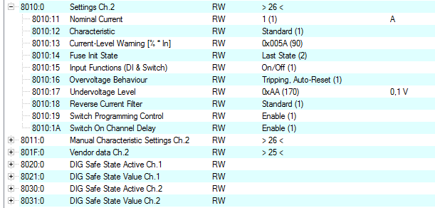
The respective parameters should be set as usual in index 8000. Settings for channel 1 index 8000:0, manual characteristic curve for channel 1 index 8001:0 (EL9227), settings for channel 2 index 8010:0, manual characteristic curve for channel 2 index 8011:0 (EL9227).
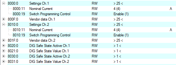
DIG Safe State Active (index 0x80n0:01) / DIG Safe State Value (index 0x80n1:01)
The setting in “DIG Safe State Active” (index 0x80n0:01) defines whether the outputs should assume a safe state in the case of a bus error. The safe state of the output in the case of a bus error is defined with “DIG Safe State Value” (index 0x80n1:01).
- “DIG Safe State Active“ = TRUE and
- “DIG Safe State Value“ = TRUE: the output is switched on.
- “DIG Safe State Active“ = TRUE and
- “DIG Safe State Value“ = FALSE: the output is switched off
- “DIG Safe State Active“ = FALSE
- The state of the output is retained. Entries in “DIG Safe State Value” (index 0x80n1:01) have no effect.
Tabular example:
DIG Safe State Active | DIG Safe State Value | Output before bus error | Output bus error occurs |
|---|---|---|---|
TRUE | TRUE | FALSE | TRUE |
TRUE | TRUE | ||
TRUE | FALSE | FALSE | FALSE |
TRUE | FALSE | ||
FALSE | FALSE / TRUE | FALSE | FALSE |
TRUE | TRUE |
| DIG Safe State By default, the EL922x have the DIG Safe State Active set to "FALSE". |
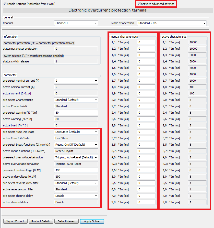
Settings via the "Settings" tab
In a more compact display, the settings can also be entered via the "Settings" tab. Proceed as follows:
- Activate the Settings input mask in the upper left corner under "Enable Settings" and confirm the message box with OK. The input masks of the most common parameters are enabled.
- Select the desired channel.
- Set the desired parameters via the preselect fields (preselect xxx). The corresponding display field (active xxx) can be found under each preselect field. The value that is currently active in the terminal is displayed there. Use the "Apply Online" button to write modified parameters to the terminal.
- For terminals with extended functionalities (EL9227), the mode of operation can also be changed here. See also chapter Process data.

To be able to set advanced parameters, enable the advanced settings at the top right, and further input masks will open (fuse init state, input functions, overvoltage behavior, undervoltage, reverse current filter, channel delay and manual characteristic). The active characteristic area is not an input mask (value field highlighted in gray). Only the values of the active characteristic curve are displayed there.
| Manual characteristic curve The maximum values for a manual characteristic curve are the values of the slow characteristic curve. |
- Import/Export
The settings can be imported or exported via this button. - Product Details
Here you can find information such as a product image with connection instructions. - Default Values
Pressing this button loads the default values into the preselect windows. These must still be confirmed with Apply Online.
Open Load Detection
The EL9227 terminals are equipped with Open Load Detection. This means that it is checked whether there is a possible wire break at the output of the terminal.
This function is available when the output is switched off.
If a voltage of typ. 0.7 / 0.8 V is detected at the output although it is switched off, this is the value of the so-called Open Load Detection. The voltage is measurable, but no high current can be sourced. This indicates that the wiring is open, such as a wire break, or that nothing is connected to the output.