EL7211, EL7211-0001
LEDs
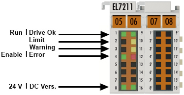
LED | Color | Meaning | |
|---|---|---|---|
RUN | green | This LED indicates the terminal's operating state: | |
off | State of the EtherCAT State Machine: INIT = initialization of the terminal | ||
flashing | State of the EtherCAT State Machine: BOOTSTRAP = function for firmware updates of the terminal | ||
flashing | State of the EtherCAT State Machine: PREOP = function for mailbox communication and different standard-settings set | ||
single flash | State of the EtherCAT State Machine: SAFEOP = verification of the Sync Manager channels and the distributed clocks. | ||
on | State of the EtherCAT State Machine: OP = normal operating state; mailbox and process data communication is possible | ||
Driver | green | on | Driver stage ready for operation |
Limit | orange | on | The LED is linked with bit 11 of the status word (MDP742 / DS402) (internal limit active) |
Warning | orange | on | The LED is linked with bit 7 of the status word (MDP742 / DS402) (warning) |
Enabled | green | on | The LED is linked with the bits 1 and 2 of status word (MDP742 / DS402) (if "Switched on" or "Operation enabled") |
Error | red | on | The LED is linked with bit 3 of the status word (MDP742 / DS402) (fault) |
+24 V via power contacts | green | on | 24 V voltage supply for the terminal is present. |
DC link supply | green | on | Voltage for the DC link supply is present. |
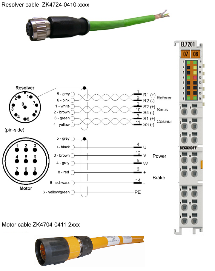
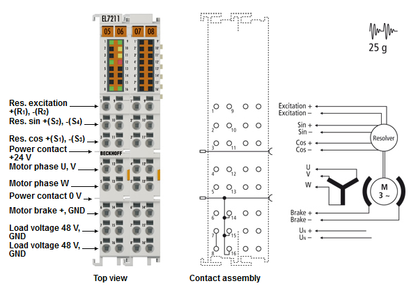
Connection
Notice | |
Fuse protection of the supply voltage The electrical protection of the load voltage must be selected in such a way that the maximum flowing current is limited to 3 times the rated current (max. 1 second)! |
Terminal point | Name | Comment |
|---|---|---|
1 | Ref + | Resolver excitation + (R1) |
2 | Sin + | Resolver sine + (S2) |
3 | Cos + | Resolver cosine + (S1) |
4 | U | Motor phase U |
5 | W | Motor phase W |
6 | Brake + | Motor brake + |
7 | 48 V | DC link supply + (8 ... 48 V) |
8 | 48 V | DC link supply + (8 ... 48 V) |
9 | Ref - | Resolver excitation - (R2) |
10 | Sin - | Resolver sine - (S4) |
11 | Cos - | Resolver cosine - (S3) |
12 | V | Motor phase V |
13 | n.c. | not connected |
14 | GND | Motor brake GND |
15 | 0 V | DC link 0 V supply |
16 | 0 V | DC link 0 V supply |
1 ' - 16' |
| not connected |