Operating modes and process data
Version notes
The single-channel EL60x1 has been developed and enhanced over a number of years. Through further development of the EL6001/EL6021 the following functional extensions have been implemented:
- from firmware (FW) 05 / hardware (HW) 03, (EL6001); firmware (FW) 04 / hardware (HW) 03, (EL6021) the objects for status monitoring and parameterization are also available from index 0x6000 (profile-specific objects) and can be parameterized in the TwinCAT System Manager, depending on the hardware.
- from firmware (FW) 06 / hardware (HW) 03, (EL6021) the command mode is supported
- from firmware 08 (EL6001) the 16-bit process data interface for sending/receiving of > 8 bit is supported
- from firmware 11 (EL6001) all integer baud rates 1000…115200 baud can be used.
Older versions of the EL6001/EL6021 do not support this functionality!
from FW/HW | ESI | Control/status/parameterizing objects area |
|---|---|---|
EL6001 01/01 EL6021 01/01 | from EL6001-0000-0000 | Index 0x300n:01 (Control-Word) Index 0x4073 (Baud rate) |
EL6001 05/03 EL6021 04/03 | from EL6001-0000-0016 | in addition to the above described objects: Index 0x6000 (COM inputs) Index 0x8000 (COM settings) |
EL6021 06/03 | from EL6021-0000-0018 | in addition to the above described objects: Index 0xB000 (Command) |
EL6001 08/03 | from EL6001-0000-0019 | in addition to the above described objects: Objects for 16-bit PDO |
EL6001 11/11 | from EL6001-0000-0020 | All baud rates 1000…115200 via explicitBaudrate implemented |
The EL6002/EL6022 devices with revision -0016 already feature objects in the 6000, 7000 and 8000 range from the first release.
 | Compatibility in the case of service Example: An EL6001/EL6021 employed and projected with Hardware 03 or higher cannot be replaced by an EL6001/EL6021 with an older hardware version (< 03)! The reverse case can be implemented without problem! |
| Process data monitoring
|
StartUp entries (hardware < 03)
| StartUp list entry For the EL6001/EL6021 with hardware < 03, the startUp entries can only be set in the transition from SafeOP to OP (S -> O). The default setting is PreOP -> SafeOP (P -> S). When creating StartUp entries, ensure that the checkbox "S -> O" is ticked (see Fig.)! |
 Fig.145: StartUp entry with transition S -> O
 Process data
As delivered, 22 bytes of user data and 1 control/status word are transferred.
The process data are generated from CoE objects 0x6000 (Inputs) and 0x7000 (Outputs) and are described in chapter Object description and parameterization in detail.
Enlarged process image 50x 16-bit
An enlarged process data interface is necessary for communication with > 8 data bits. If the terminal supports this (see Communication features) a 50-word interface can be set as an alternative to the 22-byte interface (PDOs 0x1605 and 0x1A05). This can be used with every encryption regulation (7xx, 8xx), but only makes sense with a regulation > 8 bits, e. g. 9N1. In each case the least significant bits must be occupied by the data bits, i.e. in the case of 9N1 the 9 least significant bits in the data words.
Process data of the EL60x2 from revision -0016
EL60x2 from revision -0016
Sync Manager (SM) – PDO Assignment
SM2, PDO assignment 0x1C12 | ||||
|---|---|---|---|---|
Index | Index of excluded PDOs | Size (byte.bit) | Name | PDO content |
0x1600 | - | 24.0 | COM Outputs Channel1 | Index 0x7000:01 - Ctrl__Transmit request |
Index 0x7000:02 - Ctrl__Receive accepted | ||||
Index 0x7000:03 - Ctrl__Init request | ||||
Index 0x7000:04 - Ctrl__Send continous | ||||
Index 0x7000:09 - Ctrl__Output length | ||||
Index 0x7000:11 - Data out 0 | ||||
-- | ||||
Index 0x7000:26 | ||||
0x1601 | - | 24.0 | COM Outputs Channel2 | Index 0x7010:01 |
Index 0x7010:02 | ||||
Index 0x7010:03 | ||||
Index 0x7010:04 | ||||
Index 0x7010:09 | ||||
Index 0x7010:11 | ||||
-- | ||||
Index 0x7010:26 | ||||
0x1604 (default) | - | 24.0 | COM Outputs Channel1 | Index 0x7001:01 - Ctrl |
Index 0x7000:11 - Data out 0 | ||||
-- | ||||
Index 0x7000:26 | ||||
0x1605 (default) | - | 24.0 | COM Outputs Channel2 | Index 0x7011:01 - Ctrl |
Index 0x7010:11 - Data out 0 | ||||
-- | ||||
Index 0x7010:26 | ||||
SM3, PDO assignment 0x1C13 | ||||
|---|---|---|---|---|
Index | Index of excluded PDOs | Size (byte.bit) | Name | PDO content |
0x1A00 | - | 24.0 | COM Inputs Channel1 | Index 0x6000:01 - Status__Transmit accepted |
Index 0x6000:02 - Status__Receive request | ||||
Index 0x6000:03 - Status__Init accepted | ||||
Index 0x6000:04 - Status__Buffer full | ||||
Index 0x6000:05 - Status__Input length | ||||
Index 0x6000:06 - Status__Framing error | ||||
Index 0x6000:07 - Status__Overrun error | ||||
Index 0x6000:09 - Status__Input length | ||||
Index 0x6000:11 - Data in 0 | ||||
-- | ||||
Index 0x6000:26 | ||||
0x1A01 | - | 24.0 | COM Inputs Channel2 | Index 0x6010:01 |
Index 0x6010:02 | ||||
Index 0x6010:03 | ||||
Index 0x6010:04 - Status__Buffer full | ||||
Index 0x6010:05 | ||||
Index 0x6010:06 | ||||
Index 0x6010:07 | ||||
Index 0x6010:09 | ||||
Index 0x6010:11 | ||||
-- | ||||
Index 0x6010:26 | ||||
0x1A04 (default) | - | 24.0 | COM Inputs Channel1 | Index 0x6001:01 |
Index 0x6000:11 | ||||
-- | ||||
Index 0x6000:26 | ||||
0x1A05 (default) | - | 24.0 | COM Inputs Channel2 | Index 0x6011:01 |
Index 0x6010:11 | ||||
-- | ||||
Index 0x6010:26 | ||||
Features and application notes
Optional features are generally set in the CoE directory (CAN over EtherCAT, index 0x80n0).
| Parameterization via the CoE list (CAN over EtherCAT) Please note the following general CoE information when using/manipulating the CoE parameters: - Keep a startup list if components have to be replaced - Differentiate between online/offline dictionary, ensure existence of current XML description - use “CoE reload” for resetting changes Please note especially for the EL60xx, if any changes are made to the communication settings (baud rate, data frame, feature bits), an InitRequest via the control word is required to apply the changes. |
The following CoE settings are possible from object 0x8000 and are shown below in their default settings:
 Fig.146: “CoE - Online, EL60x2 terminals” tab
 Transfer rates
The terminal has a process image of 22 bytes of user data. It possible to transmit or receive these 22 bytes every second cycle at the most.
The data is transferred from the terminal to the controller in the first cycle. In the second cycle, the controller must acknowledge that it has accepted the data.
Therefore, if the cycle time is 10 ms, 50 times 22 bytes can be transmitted per second.
With a set data frame of 8N1, each transmitted byte consists of a start bit, eight data bits and a stop bit. This is equivalent to 10 bits per user byte.
With the above mentioned settings, a continuous data transfer rate of:
• 50[1/s]*22[Byte]*10[Bit] = 11000 bps
can be achieved.
The next lower baud rate is 9600 baud. Accordingly, continuous transfer at a maximum baud rate of 9600 can be secured with a cycle time of 10 ms.
From firmware 11 the CoE 0x8000:1B supports with explicitBaudrate all baud rates 1000…115200 baud. When the baud rate is selected, the compatibility of the remote station to the set baud rate must be taken into account.
If only low quantities of data are to be transmitted or received sporadically (e.g. bar code scanner) the baud rate can also be set higher, or the cycle time can be enlarged.
If the controller cannot fetch the data quickly enough from the terminal, the data will be stored intermediately in the internal buffer of the terminal. The buffer for received data has a size of 864 bytes. If this is exhausted, all further data will be lost.
Another scenario: the controller transfers significantly more data to the terminal than the latter can transmit. For a ‘baud rate’ setting of 300 and a ‘data frame’ setting of 8N1, the terminal can only transmit 30 bytes per second. However, if more than these 30 bytes per second are received, a 128 byte transmit buffer will be written to first in this case also. Once this is full, all further data will be lost.
Transfer rate optimization: Automatic summary of received data
In serial communication, a data record is usually sent as a continuous stream of bytes. There is a pause between two data records. Based on the pauses, the terminal can recognize when a data record starts and when it ends. In this way, it can combine the bytes of a data record and pass them on to the controller in a coherent manner.
Mode of operation: Several bytes that are received in quick succession are first collected in the receive buffer. If a pause is detected after a byte (or the buffer is full), the collected receive data is transferred from the receive buffer to the process image. The "Receive Request" bit is inverted to indicate that new receive data is available.
Activate / deactivate
The automatic summary of receive data is activated in the factory setting in the CoE object 0x80n0:05 "Enable transfer rate optimization". It may be useful to deactivate it if the data that a terminal device sends is to be received as quickly as possible in the controller. Or if the end device sends continuously without pauses. If the automatic summary of received data is deactivated, each received byte is immediately transferred to the process image.
Adjustable length of the pause between two data sets
Note: This function is available in
- EL6001 from firmware 12
- EL6021, EL6021-0021 from firmware 10.
In order to change the standard time for the transfer rate optimization, the waiting time in bit times 1...254 must be entered in the CoE object 0xB000:01 in the hi-byte 0x24 and in the low-byte
Example: 0x10 (16dec) for a waiting time of 16 bit times:
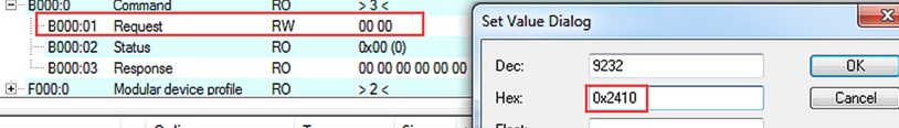 Fig.147: Example for setting the waiting time of 16 bit times
At 115.2 kBaud this corresponds to 139 µs: (1/115200 [bit/s]) * 16 [bit]. After a gap of this length, the data is automatically copied to the process image.
Continuous transmission of data
Usually the EL60xx terminal automatically decides when to send the data bytes contained in the buffer. For many applications it is helpful to have a continuous data stream. For this purpose, the Beckhoff EL60xx terminals feature the ‘Enable send FIFO data continuous’ setting in the Settings object. If this switch is set.
- The internal send buffer (128 bytes) must be filled first. To this end, data will be sent from the controller to the terminal as in a normal data transfer.
- Data transfer from the buffer commences with a rising edge of the bit “Send continuous”
- If the data has been transferred, the terminal informs the controller by setting the “InitAccepted” bit. “Init accepted” is cleared with “Send continuous”.
This setting enables up to 128 bytes to be transferred without long delays, even with slower EtherCAT cycle times and high baud rates.
The terminal tries to leave as little distance as possible between the telegrams by seamlessly following each stop bit with the next start bit. Nevertheless, in two-channel mode high baud rates may result in short pauses between telegrams. A 20-byte data block may be sent in two blocks of 5 and 15 or 7 and 13 telegrams, for example, or with a different distribution. In a two-channel terminal channel 1 is given priority.
Prioritization
Since received data normally cannot be repeated, it has a higher priority than data to be transmitted.
Furthermore, the priority decreases as the channel number increases. Hence, the reception of data on channel 1 has the highest priority.
Command mode
From firmware 06 / revision -0018 the EL6021 supports the so-called command mode. Certain terminal functions can be used and controlled through optional combination and/or sequence of commands. The following functions are currently supported:
- Multi-data frame feature: (from firmware 06) change of coding during ongoing data communication (sending)
To this end the send buffer of the terminal should be filled with the bytes to be sent (note the maximum buffer size). As soon as the send process is started via the control word, the first n bytes are sent based on coding A, the remaining bytes in the buffer are sent with coding B. The buffer can then be refilled and sent accordingly. Example: The first byte is sent with mark parity, the remaining bytes with space parity.
Sequence: - After each startup/restart of the EL60xx EtherCAT slave the parameterization has to be repeated. The command function is not stored in the event of a power failure.
- Activation of SendContinuous mode through writing of 0x1 after 0x8000:04
- Activation of the multi-data frame feature through writing of 0x2001 after request 0xB000:01
Check that 0xB000:02 = 0 - Specify coding A through writing of 0x2100 + [date frame code] after 0xB000:01
Example: 8E2 = 0x12 --> write value 0x2112
Check that 0xB000:02 = 0 - Specify n bytes to be sent in coding A through writing of 0x2200 + [n] after 0xB000:01
Check that 0xB000:02 = 0 - Specify coding B through writing of 0x2300 + [date frame code] after 0xB000:01
Check that 0xB000:02 = 0 - Start sending through rising edge of Ctrl SendContinuous
- Terminal signals completed transfer through InitAccepted = 1. InitAccepted is reset with SendContinuous.
- CmdNameMeaning0x2000 + ControlByteCmdControlByteBit 0: Enable MultiDataFrame feature Bit 1..7: do not use0x2100 + Valuefirst data frameselect preferred value from data frame table0x2200 + NoOfBytesNo of bytesNo of bytes transfered with first data frame0x2300 + Valuesecond data frameselect prefered value from data frame table
- Note: In this mode coding 8M1 and 8S1 is also supported, although this coding cannot be selected via 0x8000:15.
- Further features can be implemented on request
Data transfer examples
Initialization
Initialization is performed prior to the first transmission/reception. The terminal is thereby parameterized with the data from the corresponding Settings object.
Note: x80n0:01 "Enable RTS/CTS" is TRUE by default, the firmware expects signals here. If these lines are not occupied, this setting must be set to FALSE for this example.
Procedure:
- Set “Init request” to 1
- The terminal confirms successful initialization by setting “Init accepted”
- Reset “Init request”
- The terminal sets “Init accepted” to 0
The terminal is now ready for data exchange.
Data transmission from the controller to the terminal (send 2 characters)
- Set “Output length” to 2
- Fill “Data Out 0” and “Data Out 1” with user data
- Change the state of “Transmit request”
- The terminal acknowledges receipt of the data by changing the state of the “Transmit accepted” bit.
Data transmission from the terminal to the controller (receive characters)
- The terminal indicates that there is new data in the process image by changing the state of the “Receive request” bit.
- The number of bytes received is written in “Input length”
- The controller acknowledges acceptance of the bytes by changing the state of “Receive request”