EL5122 - Connection
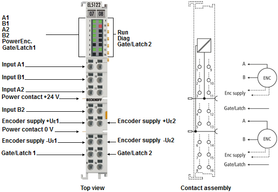 Fig.4: EL5122 - Connection
Terminal point | No. | Comment |
|---|---|---|
A1 | 1 | Encoder input A1 |
B1 | 2 | Encoder input B1 |
A2 | 3 | Encoder input A2 |
B2 | 4 | Encoder input B2 |
+Ue1 | 5 | Encoder supply (5 V default, parameterizable 12 V, 24 V) |
-Uo1 | 6 | 0 V encoder supply |
Gate/Latch1 | 7 | Gate/Latch combination input for encoder 1 |
n.c. | 8 | Do not connect the terminal point |
n.c. | 9 | Do not connect the terminal point |
n.c. | 10 | Do not connect the terminal point |
n.c. | 11 | Do not connect the terminal point |
n.c. | 12 | Do not connect the terminal point |
+Ue2 | 13 | Encoder supply (5 V default, parameterizable 12 V, 24 V) |
-Uo2 | 14 | 0 V encoder supply |
Gate/Latch2 | 15 | Gate/Latch combination input for encoder 2 |
n.c. | 16 | Do not connect the terminal point |
 | Setting the encoder supply via index 0x8001:17 The encoder supply is set centrally for both channels via the index 0x8001:17 (channel 1). The corresponding index 0x8011:17 of the second channel has no parameterization function. |
Notice | |
Setting the encoder supply voltage
|