Process data and configuration
The principles for the oversampling function and the mode of operation of the EL5101-0011 with the use of the SYNC0 and SYNC1 pulses are explained in the section "Principles of the oversampling function".
The setting of the various parameters using the Beckhoff TwinCAT System Manager is described in the following chapter. The EL5101-0011 offers the following process data:
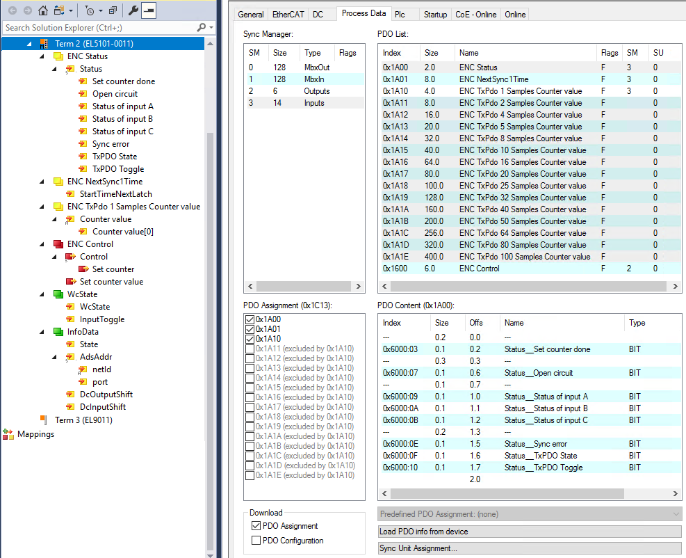
EL5101-0011 - Process data (default)
Oversampling settings, distributed clocks (DC)
The oversampling factor can be set on the "DC" tab (see figure below). The oversampling factor n is set to 1 in the delivery condition. When an entry is selected in the dialog, the correct sampling ratio at distributed clock level and the correct number of process data to be transferred are set automatically.
 | Sampling frequency If an oversampling factor is required that does not appear in the list, the user has to specify the ratio between the SYNC0 pulse and the SYNC1 pulse within the permitted limits, based on the information found in "Principles of the oversampling function". Please refer to the note “Maximum sampling frequency / minimum cycle time”. |
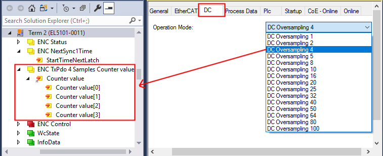 Fig.177: Setting of the oversampling factor n = 4 and display of the process data to be transferred
Sampling times TSYNC0 apply to EL5101-0011:
Oversampling factor | Cycle time TSYNC1 | ||||
|---|---|---|---|---|---|
500 µs | 1,000 µs | 2,000 µs | 5,000 µs | 10,000 µs | |
1 | 500.00 µs | 1,000.00 µs | 2,000.00 µs | 5,000.00 µs | 10,000.00 µs |
2 | 250.00 µs | 500.00 µs | 1,000.00 µs | 2,500.00 µs | 5,000.00 µs |
4 | 125.00 µs | 250.00 µs | 500.00 µs | 1,250.00 µs | 2,500.00 µs |
5 | 100.00 µs | 200.00 µs | 400.00 µs | 1,000.00 µs | 2,000.00 µs |
8 | 62.50 µs | 125.00 µs | 250.00 µs | 625.00 µs | 1,250.00 µs |
10 | 50.00 µs | 100.00 µs | 200.00 µs | 500.00 µs | 1,000.00 µs |
16 | 31.25 µs | 62.50 µs | 125.00 µs | 312.50 µs | 625.00 µs |
20 | 25.00 µs | 50.00 µs | 100.00 µs | 250.00 µs | 500.00 µs |
25 | 20.00 µs | 40.00 µs | 80.00 µs | 200.00 µs | 400.00 µs |
32 | 15.63 µs | 31.25 µs | 62.50 µs | 156.25 µs | 312.50 µs |
40 | 12.50 µs | 25.00 µs | 50.00 µs | 125.00 µs | 250.00 µs |
50 | 10.00 µs | 20.00 µs | 40.00 µs | 100.00 µs | 200.00 µs |
64 | Not permissible, because TSYNC0 < 10 µs | 15.63 µs | 31.25 µs | 78.125 µs | 156.25 µs |
80 | Not permissible, because TSYNC0 < 10 µs | 12.50 µs | 25.00 µs | 62.50 µs | 125.00 µs |
100 | Not permissible, because TSYNC0 < 10 µs | 10.00 µs | 20.00 µs | 50.00 µs | 100.00 µs |
Sampling frequencies FSYNC0 apply to EL5101-0011:
Oversampling factor | Cycle time TSYNC1 | ||||
|---|---|---|---|---|---|
500 µs | 1,000 µs | 2,000 µs | 5,000 µs | 10,000 µs | |
1 | 2.0 kSps | 1.0 kSps | 0.5 kSps | 0.2 kSps | 0.1 kSps |
2 | 4.0 kSps | 2.0 kSps | 1.0 kSps | 0.4 kSps | 0.2 kSps |
4 | 8.0 kSps | 4.0 kSps | 2.0 kSps | 0.8 kSps | 0.4 kSps |
5 | 10.0 kSps | 5.0 kSps | 2.5 kSps | 1.0 kSps | 0.5 kSps |
8 | 16.0 kSps | 8.0 kSps | 4.0 kSps | 1.6 kSps | 0.8 kSps |
10 | 20.0 kSps | 10.0 kSps | 5.0 kSps | 2.0 kSps | 1.0 kSps |
16 | 32.0 kSps | 16.0 kSps | 8.0 kSps | 3.2 kSps | 1.6 kSps |
20 | 40.0 kSps | 20.0 kSps | 10.0 kSps | 4.0 kSps | 2.0 kSps |
25 | 50.0 kSps | 25.0 kSps | 12.5 kSps | 5.0 kSps | 2.5 kSps |
32 | 64.0 kSps | 32.0 kSps | 16.0 kSps | 6.4 kSps | 3.2 kSps |
40 | 80.0 kSps | 40.0 kSps | 20.0 kSps | 8.0 kSps | 4.0 kSps |
50 | 100.0 kSps | 50.0 kSps | 25.0 kSps | 10.0 kSps | 5.0 kSps |
64 | Not permissible, because FSYNC0 > 100 kSps | 64.0 kSps | 32.0 kSps | 12.8 kSps | 6.4 kSps |
80 | Not permissible, because FSYNC0 > 100 kSps | 80.0 kSps | 40.0 kSps | 16.0 kSps | 8.0 kSps |
100 | Not permissible, because FSYNC0 > 100 kSps | 100.0 kSps | 50.0 kSps | 20.0 kSps | 10.0 kSps |
"StartTimeNextLatch"
The process data "StartTimeNextLatch" (index 0x1A01) is activated by default.
The “StartTimeNextlatch” process data is 32 bits wide. During each process data cycle the time is specified at which the next SYNC1 pulse and therefore the next block of sample values begins. “StartTimeNextLatch” thus changes in each cycle by the amount of that task cycle time with which this terminal is operated. This time specification is based on the terminal’s local Distributed Clocks time. The terminal maps only the 64-bit distributed clocks time.
In this way all samples can be synchronized with other time data within the EtherCAT bus based on the known oversampling factor.
Sample:
The terminal supplies in the regarded cycle with
cycle time = 1 ms (= 1,000,000 ns) and
oversampling factor n = 20,
a “StartTimeNextLatch” of 503,330,625,067,077,000dec and 20 measured values (counter value) of 32 bits each as process data.
The time of measurement of the 5th supplied position value is now to be determined, i.e. the Distributed Clocks time at which the 5th position value was determined.
The currently delivered set of 20 counter values was started at the time:
503,330,625,067,077,000 – 1,000,000 (cycle time) = 503,330,625,066,077,000 ns.
The time interval between the samples is 1.000.000/20 = 50.000 ns.
The 5th position value was thus determined at the time:
503,330,625,066,077,000 + ((5 - 1) * 50,000) = 503,330,625,066,027,000 ns
Special oversampling factor and Shift Time for the SYNC0 pulse
Notice | |
CAUTION! Risk of device damage! If these settings are changed in the System Manager, no plausibility checks are carried out on the software side. |
Setting the counter value - referencing:
Since incremental encoders do not deliver an unambiguous position value after switching on, a homing must be carried out.
The EL5101-0011 offers the option to set the reference point manually via "Set counter" (index 0x7000:03).
“Set counter” (index 0x7000:03)
- The value to be set as reference value (default: 0) is written in “Set counter value” (index 0x7000:11).
- The function is activated by setting the bit in “Set counter” (index 0x7000:03) to TRUE.
- The value from “Set counter value” (index 0x7000:11) is written in “counter value” (index 0x6000:11).
- The value of the bit in “Set counter done” (index 0x6000:03) is set to TRUE.
- After re-activation of "Set counter" (Index 0x7000:03), the next reference value can be written in "counter value" (Index 0x6000:11) only if the value of the "Set counter done" bit (index 0x6000:03) is FALSE.
Open circuit detection
- A separate open circuit detection can be activated for each of the channels A, B and C (index 0x8000:0B, 0x8000:0C, 0x8000:0D).
- The open circuit detection for channels A and B is activated by default.
- A differential voltage of -0.475 V > Vid >+0.475 V (typical, subject to change) is detected as an open circuit.
- If an open circuit is detected, it is indicated as process data "Open circuit” = TRUE. The bit in object 0x6000:07 is set. An open circuit is indicated separately in indices 0xA000:01 (track A), 0xA000:02 (track B) and 0xA000:03 (track C).
- “TxPDO state” also becomes TRUE if an open circuit is detected, since invalid data have to be assumed.
Further cyclic information
Furthermore, the EL5101-0011 offers the following cyclic information:
Variable | Meaning |
|---|---|
Sync error | In DC mode: indicates whether a synchronization error occurred in the expired cycle. This means a SYNC signal was triggered in the terminal, although no new process data were available (0=OK, 1=NOK). |
TxPDO State | Indicates whether an error has occurred (= TRUE). TxPDO State is set to TRUE if internal errors are detected or an open circuit is signaled, since invalid data must be assumed. |
DcOutputShift, DcInputShift | In these static variables the System Manager announces the shift time to which this terminal has been set. The value is set once on activating/calculating the configuration and also depends on the customer-specific settings in the extended slave settings. It can be linked to offset calculations in the PLC. |
StartTimeNextLatch | See chapter "StartTimeNextLatch" |