Process data
Data flow
The amplitude values are measured with 16-bit resolution and provided as oversampling packets in the process image for cyclic transmission.
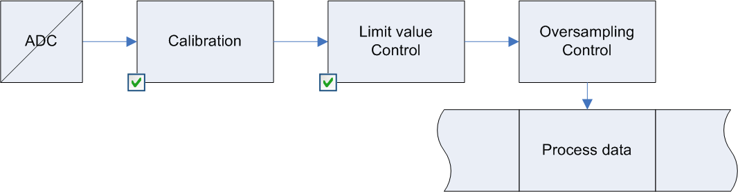 Fig.98: Process data flow EL3773
Data processing
The data processing is done simultaneously for all channels in the EL3773 with 16-bit conversion in the ADC
Scaling related to the respective (constant) measuring range:
1. Vendor calibration (0x80p0:0B)
Activation: CoE 0x80p0:0B
X1 = (XADC - OffsetVendor) * GainVendor
This produces the following signed integer value representation:
|
Input signal |
Value | ||
|---|---|---|---|
|
Voltage |
Current |
Decimal |
Hexadecimal |
|
410 V |
1.5 A |
32767 |
0x7FFF |
|
205 V |
0.75 A |
16383 |
0x3FFF |
|
0 V |
0 A |
0 |
0x0000 |
|
-205 V |
-0.75 A |
-16383 |
0xC001 |
|
-410 V |
-1.5 A |
-32767 |
0x8000 |
Signed integer: the negative output value is represented in two’s complement (negated + 1). Maximum representation range for 16 bits = -32768 to +32767dec.
3. Limit value evaluation (0x80p0:13, 0x80p0:14)
Display in the status word of the channel
If the value exceeds or falls below these values, which can be entered in the indices 0x80p0:13 and 0x80p0:14, then the bits in the indices 0x60p0:03 and 0x60p0:05 are set accordingly (see example below).
The entry 0x80p0:07 serves to activate the limit value monitoring.
Output limit n (2-bit):
- 0: not active
- 1: One or more values <= Limit n
- 2: One or more values >= Limit n
- 3: Cases 1 and 2 simultaneously
 | Linking in the PLC with 2-bit values The limit information consists of 2 bits. Limitn can be linked to the PLC or a task in the System Manager:
|
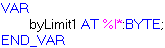
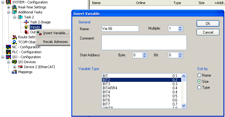 Fig.99: Linking of 2-bit variable to additional task
Example of voltage measurement with EL3773:
Channel 1; Limit 1 and Limit 2 enabled, Limit 1 = 100 V, Limit 2 = 200 V, representation: signed integer
Entry in index (Limit 1): 0x8000:13
(100 V / 410 V) x 216 / 2 - 1 = 7991dec
Entry in index (Limit 2): 0x8000:14
(200 V / 410 V) x 216 / 2 - 1 = 15983dec
Output:
Input channel 1 | Index 0x6000:03 | Index 0x6000:05 |
|---|---|---|
50 V | 0x01hex, (Limit 1, limit value undershot) | 0x01hex, (Limit 2, limit value undershot) |
100 V | 0x03hex, (Limit 1, limit value reached) | 0x01hex, (Limit 2, limit value undershot) |
150 V | 0x02hex, (Limit 1, limit value exceeded) | 0x01hex, (Limit 2, limit value undershot) |
210 V | 0x02hex, (Limit 1, limit value exceeded) | 0x02hex, (Limit 2, limit value exceeded) |
4. Provision in the process data
The influencing parameters can be changed in the CoE of the respective channel.
 Fig.100: User settings and vendor calibration in the CoE online directory
 | Changes in the CoE directory In case of changes to the CoE default parameters, it is essential that corresponding values are entered in the start-up list, so that in the case of exchange the EL3773 operates again as foreseen in the application. |
Predefined PDO Assignment
The "Predefined PDO Assignment" enables a simplified selection of the process data.
The desired function is selected on the lower part of the "Process Data" tab. As a result, all necessary PDOs are automatically activated and the unnecessary PDOs are deactivated.
8 PDO assignments are available:
Name | SM3, PDO assignment, meaning |
|---|---|
Synchronous | 0x1A00, 0x1A01, 0x1A10, 0x1A11, 0x1A20, 0x1A21, 0x1A30, 0x1A31, 0x1A40, 0x1A41, 0x1A50, 0x1A51 |
Synchronous oversampling 2 | 0x1A00, 0x1A02, 0x1A10, 0x1A12, 0x1A20, 0x1A22, 0x1A30, 0x1A32, 0x1A40, 0x1A42, 0x1A50, 0x1A52 |
Synchronous oversampling 4 | 0x1A00, 0x1A03, 0x1A10, 0x1A13, 0x1A20, 0x1A23, 0x1A30, 0x1A33, 0x1A40, 0x1A43, 0x1A50, 0x1A53 |
Synchronous oversampling 8 | 0x1A00, 0x1A05, 0x1A10, 0x1A15, 0x1A20, 0x1A25, 0x1A30, 0x1A35, 0x1A40, 0x1A45, 0x1A50, 0x1A55 |
Synchronous oversampling 16 | 0x1A00, 0x1A07, 0x1A10, 0x1A17, 0x1A20, 0x1A27, 0x1A30, 0x1A37, 0x1A40, 0x1A47, 0x1A50, 0x1A57 |
Synchronous oversampling 32 | 0x1A00, 0x1A0A, 0x1A10, 0x1A1A, 0x1A20, 0x1A2A, 0x1A30, 0x1A3A, 0x1A40, 0x1A4A, 0x1A50, 0x1A5A |
Synchronous oversampling 64 | 0x1A00, 0x1A0D, 0x1A10, 0x1A1D, 0x1A20, 0x1A2D, 0x1A30, 0x1A3D, 0x1A40, 0x1A4D, 0x1A50, 0x1A5D |
DC (activate Mode on DC tab) | 0x1A00, 0x1A05, 0x1A10, 0x1A15, 0x1A20, 0x1A25, 0x1A30, 0x1A35, 0x1A40, 0x1A45, 0x1A50, 0x1A55 |
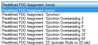 Fig.101: EL3773 Selection dialog "Predefined PDO Assignment"
Process image
The EL3773 is inserted into the configuration by default with the 10-fold oversampling process image and DC timestamp:
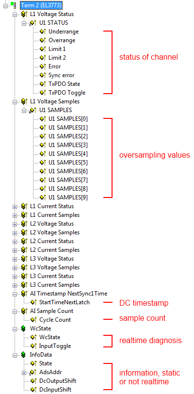 Fig.102: Process image of the EL3773 in the TwinCAT System Manager
It is urgently recommended to evaluate the offered diagnostic values in the controller, e.g. see the Notes page.
In particular the EL3773 offers the following cyclic information:
Variable | Meaning |
|---|---|
Status word | |
Overrange | Value after calibration > 0x7FFF |
Underrange | Value after calibration < 0x8000 |
SyncError | - In DC mode: indicates whether a synchronization error occurred in the expired cycle. |
StartTimeNextLatch | In the 64-bit-wide process data StartTimeNextLatch, as was also the case with previous EL37xx terminals, the time is specified in each process data cycle when the next SYNC1 pulse and thus the next block of sample values begins, referenced to the currently transmitted block. StartTimeNextLatch thus changes in each cycle by the amount of that task cycle time with which this terminal is operated. This time specification is based on the terminal’s local Distributed Clocks time. Example: |
Cycle Count | The cycle counter is incremented by one unit with each process data cycle. The CycleCounter enables the higher-level controller to check whether a data record has possibly been omitted or transmitted twice. In that case the DC shift time of the terminal usually has to be adapted. |
DcOutputShift, DcInputShift | In these static variables the System Manager announces the shift time to which this terminal has been set. The value is set once on activating/calculating the configuration and also depends on the customer-specific settings in the extended slave settings. |
Correlation between timestamp and process data
The figure "Timing relationship between SYNC signals and SyncManager interrupt" illustrates the function and the timing relationship between time stamp and measured values.
For explanation::
- shown is an example for oversampling factor = 5
- the SYNC0 signal in the terminal triggers the AD conversion and fills the internal buffer with 5 measured values (A)
- SYNC1 runs synchronously with the cycle time, which triggers the supply of the filled buffer as process date and simultaneously fetches the StartTimeNextLatch from the local DistributedClock (B)
- the data block is assembled together with the next LatchTime
- the next EtherCAT cycle fetches this data (C)
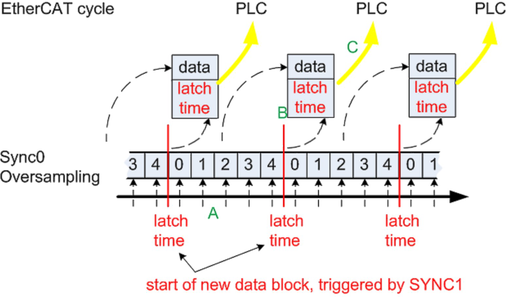 Fig.103: Timing relationship between SYNC signals and SyncManager interrupt
Since different input filters (see CoE setting 0x8000:15 [95]) also result in different propagation delays within the terminal, these can be compensated again via CoE object 0x805D:12 so that the time stamp continues to match the measured values. Please refer to the following table to find the appropriate value for your input filter.
Filter Setting | Signal Runtime | Correction Value |
|---|---|---|
15000 Hz | 50 µs | -50000 ns |
5000 Hz | 150 µs | -150000 ns |
2500 Hz | 300 µs | -300000 ns |
1500 Hz | 500 µs | -500000 ns |
1000 Hz | 750 µs | -750000 ns |
500 Hz | 1.5 ms | -1500000 ns |
200 Hz | 3.75 ms | -3750000 ns |
However, since only one DCTimeStampShift value can be set per terminal, it may make sense to perform this conversion in the PLC first if the input filters are different for each channel.
Control/status word
Status word
The status word (SW) is located in the input process image, and is transmitted from terminal to the controller.
|
Bit |
SW.15 |
SW.14 |
SW.13 |
SW.12 |
SW.11 |
SW.10 |
SW.9 |
SW.8 |
|
Name |
TxPDO Toggle |
TxPDO State |
Sync error |
- |
- |
- |
- |
- |
|
Bit |
SW.7 |
SW.6 |
SW.5 |
SW.4 |
SW.3 |
SW.2 |
SW.1 |
SW.0 |
|
Name |
- |
ERROR |
Limit 2 |
Limit 1 |
Overrange |
Underrange | ||
|
Bit |
Name |
Description | |
|---|---|---|---|
|
SW.15 |
TxPDO Toggle |
1bin |
Toggles with each new analog process value |
|
SW.14 |
TxPDO State |
1bin |
TRUE in the case of an internal error |
|
SW.13* |
Sync error |
1bin |
TRUE (DC mode): a synchronization error occurred in the expired cycle. |
|
SW.6 |
ERROR |
1bin |
General error bit, is also set together with overrange and underrange |
|
SW.5 |
Limit 2 |
1bin |
See Limit |
|
SW.4 |
1bin | ||
|
SW.3 |
Limit 1 |
1bin |
See Limit |
|
SW.2 |
1bin | ||
|
SW.1 |
Overrange |
1bin |
Analog input signal lies above the upper permissible threshold for this terminal |
|
SW.0 |
Underrange |
1bin |
Analog input signal lies under the lower permissible threshold for this terminal |
Control word
The EL3773 has no control word
Synchronization, trigger and conversion time
The EL3773 generally operates in oversampling mode. It can be operated with and without Distributed Clocks activated.
Distributed Clocks activated
- the EtherCAT system-wide synchronized Distributed Clocks also encompass this EL3773
- the terminal then operates synchronously with all other DC devices
- the sampling clock is derived from the local DC in the EtherCAT slave controller (SYNC0: Oversampling, SYNC1: Provision of the data)
Advantages
- several EL3773 record the measured values of all their channels synchronously
- accurate time stamp of the individual samples
The following limit values are to be observed
- minimum sampling time 100 µs (10,000 kSps)
- only non-periodic values are permissible for the sampling rate
- the PDO StartTimeNextlatch can only be used/activated with cycle times > 100 µs
Table of sampling times
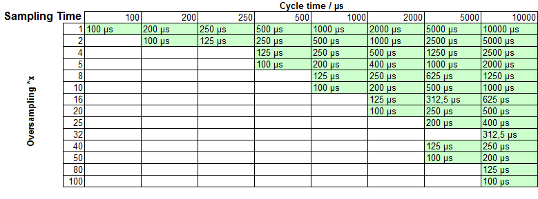 Fig.104: Samplingtime
 | Supported configurations Configurations that require sampling times that are not divisible by 500 ns are not supported. |
Example: a 4000µs-cycle can be used with an oversampling factor of 64, since the sampling time is 62.5µs and therefore divisible by 500ns.
The minimum EtherCAT cycle time for the EL3773 is 100 µs. In order to activate Distributed Clocks, "DC" is to be selected in the Predefined PDO list, so that amongst others the time stamp PDO is selected
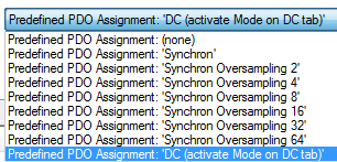 Fig.105: EL3773 Selection dialog "Predefined PDO Assignment"
 The permissible oversampling rates are set via the System Manager DC tab:
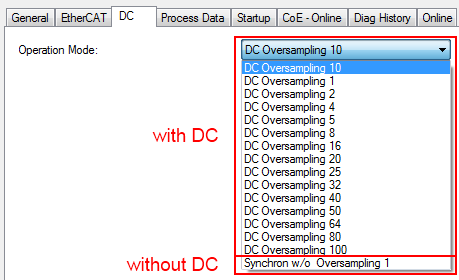 Fig.106: Setting of the oversampling rates via System Manager, "DC" tab
Distributed Clocks not activated
- the EL3773 operates according to an internal clock, which is synchronized to the EtherCAT cycle time. The trigger point in this case is the access to the input Sync Manager SM3.
- As a result the EL3773 can compensate fluctuations in the cycle time to a large extent
- The EL3773 can thus be used in systems that have no Distributed Clocks functionality. The time accuracy of the measured values is reduced, however.
The EtherCAT cycle time must be selected such that
- it is not less than 100 µs
- the oversampling interval does not produce a non-periodic time value – for example, 33.3 µs is not allowed for the oversampling cycle
The Distributed Clock is to be deactivated in the DC tab
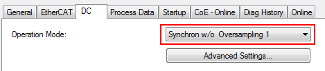 Fig.107: Deactivation of the Distributed Clock in the "DC" tab
The permissible oversampling rates are then set via the System Manager:
Fig.101: EL3773 Selection dialog "Predefined PDO Assignment"