Settings
Presentation, index 0x80x0:02
The measured value output is set in factory to two's complement representation (signed integer).
Index 0x80x0:02 offers the possibility to change the method of representation of the measured value.
-
Signed integer:
The measured value is presented in two’s complement format.
Maximum display range EL3351:
|
Measuring range |
Measuring range |
Output value |
|---|---|---|
|
+ 12 V |
+ 20 mV |
7F FF FF FF |
|
+ 6 V |
+ 10 mV |
3F FF FF FF |
|
+ 0 V |
+ 0 V |
00 00 00 00 |
|
- 0 V |
- 0 V |
FF FF FF 00 |
|
- 6 V |
- 10 mV |
C0 00 00 00 |
|
- 12 V |
- 20 mV |
80 00 00 01 |
-
Absolute value with MSB as sign:
The measured value is output in magnitude-sign format.
Maximum display range EL3351:
|
Measuring range |
Measuring range |
Output value |
|---|---|---|
|
+ 12 V |
+ 20 mV |
7F FF FF FF |
|
+ 6 V |
+ 10 mV |
3F FF FF FF |
|
+ 0 V |
+ 0 V |
00 00 00 00 |
|
- 0 V |
- 0 V |
80 00 00 00 |
|
- 6 V |
- 10 mV |
C0 00 00 01 |
|
- 12 V |
- 20 mV |
FF FF FF FF |
right adjust 24 bits:
The measured value is output with a resolution of 24 bit.
Maximum display range EL3351:
|
Measuring range |
Measuring range |
Output value |
|---|---|---|
|
+ 12 V |
+ 20 mV |
00 7F FF FF |
|
+ 6 V |
+ 10 mV |
00 3F FF FF |
|
+ 0 V |
+ 0 V |
00 00 00 00 |
|
- 0 V |
- 0 V |
FF FF FF FF |
|
- 6 V |
- 10 mV |
FF C0 00 00 |
|
- 12 V |
- 20 mV |
FF 80 00 00 |
Siemens Bits, Index 0x80x0:05
If this bit is set, status displays are superimposed on the lowest three bits. In the error case "overrange" or "underrange", bit 0 is set.
Undershoot and overshoot of the measuring range (under-range, over-range), index 0x60x0:01,0x60x0:02
Undershoot:
Index 0x60x0:01 and index 0x60x0:07 (underrange and error bit) are set. The linearization of the characteristic curve is continued with the coefficients of the under-range limit up to the limit stop of the A/D converter or to the minimum value of 0x80 00 00 01.
Overshoot:
Index 0x60x0:02 and index 0x60x0:07 (overrange and error bit) are set. The linearization of the characteristic curve is continued with the coefficients of the over-range limit up to the limit stop of the A/D converter or to the maximum value of 0x7F FF FF FF .
In the event of overrange or underrange on UD, the red error LED comes on; Uref has no influence on the error LED.
Filter and conversion times
The EL3351 has a 2-channel DeltaSigma ADC, which alternately samples UDiff and URef at a high sample rate (several MHz), filters with sinc5 and then averages in a configurable manner. This results in the following consequences:
- The acquisition of both channels takes place alternately, so-called multiplex. As soon as the measured value of a channel (UDiff or URef) is available, it is converted by the internal µC of the terminal (see data flow) and transported via EtherCAT by PDO.
The PDOs "AlBridge Inputs - Value" and "AlSupply Inputs - Value" are updated independently of each other. - This must be taken into account if fast load changes are to be tracked with the EL3351. The alternating updating of the channels appears as follows, e.g. in TwinCAT Scope with the slow filter "5 Hz":
- The respective PDO TxPDO Toggle also indicates that there is a new value in Value by changing the value.
- The filtering according to CoE x8000:15 "Filter Setting" is always effective and cannot be switched off, CoE "Enable Filter" has no function either in channel 1 or in channel 2.
- The filtering can only be set for both channels equally via x8000:15 channel1, CoE x8010:15 in channel 2 has no function.
- The filter acts as a notch filter (notch filter, average filter with adjustable window width). Notch filter means that the filter has zeros (notches) in the frequency response at the named filter frequency and multiples thereof, i.e. it fades out these frequencies. So to filter out 50 Hz, the 50 or the 10 Hz filter can be used. However, since usually all lower frequencies than the cutoff frequency are to be measured, the setting "50 Hz" is to be used in this case.
- The selectable filter frequency according to index 0x8000:15 acts in the ADC and configures the averaging width and thus the update rate. The higher the filter frequency, the faster the conversion time.
If a PDO (URef or UD) is deactivated via the PDO management, the specified times are halved.
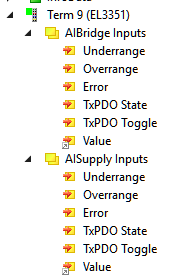 Fig.141: TwinCAT tree "AIBridge Inputs" and "AISupply Inputs"
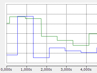 Fig.142: TwinCAT Scope: alternate update of the channels
 Fig.143: Typical frequency response of a notch filter set to 50 Hz
Typical conversion times EL3351
Filter frequency | Conversion time (update time) Normal operation (2 channels) |
|---|---|
5 Hz | 800 ms |
10 Hz | 400 ms |
50 Hz | 82 ms |
60 Hz | 69 ms |
100 Hz | 42 ms |
500 Hz | 10 ms |
1000 Hz | 6 ms |
2000 Hz | 4 ms |
3750 Hz | 3 ms |
7500 Hz | 3 ms |
15000 Hz | 3 ms |
30000 Hz | 2.5 ms |
Table 2: Conversion times in relation to the filter frequencies (subject to change!)