Sample implementation of a PTC sensor
The example below illustrates the implementation of a PTC sensor, in particular a platinum sensor (Pt sensor), based on the RTD table and according to DIN EN 60751.
Example for the implementation of a PTC sensor with the RTD lookup table
The general procedure is explained in chapter Lookup table. The example describes the implementation of table for a Pt500 sensor.
Description | Problem | Approach | |
|---|---|---|---|
For Pt sensors, tables with several 100 entries in 1°C steps are available. | Total number of interpolation points is exceeded. |
| |
The manufacturer tables contain universal values | The table values should be adjusted to the specific sensor type | For different Pt sensors, the table entries have to be multiplied with the R0 value. R0 indicates the resistance at 0°C. The sensor designation is based on the temperature value. | |
Pt sensor | R0 (resistance at 0°C) | ||
Pt100 | 100 | ||
Pt500 | 500 | ||
Pt1000 | 1000 | ||
For the Pt500 sensor, the following CoE entries can be selected and edited with the following XML file (Download: ZIP):
CoE Entry | Entry |
|---|---|
0x8001:01 Distance in Degrees | 10 |
0x8001:02 Amount of Entries | 60 |
0x8001:03 Start Temperature | -40 |
0x8001:04 Conversion Factor | 10 |
0x8001:05 Value 1 | 4247 |
0x8001:0x further table entries | ..... |
Example for the implementation of a PTC sensor, programmable according to DIN 60751 for Pt sensors
The implementation according to DIN EN 60751 is described in the section Programmable_according_to_DIN_60751_for_Pt sensors. The parameters A, B, C are already stored in the CoE. Only the temperature range and the R0 parameter for the specific sensor need to be added. R0 indicates the resistance at 0°C. The sensor designation is based on the temperature value. The CoE entry has to be adjusted for the specific sensor.
Pt sensor | CoE Entry 0x8003:03 |
|---|---|
Pt100 | 100 |
Pt200 | 200 |
Pt500 | 500 |
Pt1000 | 1000 |
Comparison of implementation via RTD table and according to DIN EN 60751
If we now compare the course of the resistance values as a function of temperature, by the RTD table and according to DIN EN 60751, it becomes clear that both implementation methods provide almost the same result. Due to the easier implementation, the parameterization according to DIN 60571 is preferable.
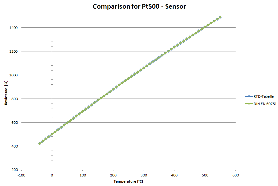 Fig.176: Comparison of Pt500 sensor implementation