RTD measurement in EL32xx
Notice | ||
 | Further documentation for I/O components with analog in and outputs Also pay attention to the further documentation: I/O Analog Manual which is available in the Beckhoff Information-System and for download on the Beckhoff website www.beckhoff.com on the respective product pages! The content includes the basics of sensor technology and information on analog measured values. | |
The EL32xx-xxxx series analog input terminals offer the option to take a resistance measurement, as well as the evaluation of a resistance sensor by computational transformation R→T. Common characteristic curves are implemented in the terminal for directly converting the resistance value into a temperature (see IO Analog Manual chapter Overview of implemented RTD transformations). In addition, resolutions, output formats and scaling can be adjusted depending on the device.
The analog input terminals of the EL32xx-xxxx series measure the connected resistance directly ratiometrically by voltage comparison and convert this into a temperature if required. This is performed as shown in the diagram in the following figure:
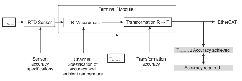 Fig.26: Representation of the measurement of the resistance and calculation of the temperature
R measurement
The measurement is performed ratiometrically:
A constant voltage of 2.5 V is fed through a known reference resistor Rreference and through the sensor Rsensor. The size of the reference resistor is 5 kΩ (except EL3024-0200: Rreference = 120 kΩ).
By voltage comparison of UR, Reference and UR, Sensor, the sensor resistance Rsensor can be determined.
The measuring current at the sensor is thus dependent on the sensor resistance Rsensor, which must be taken into account when considering any sensor self-heating.
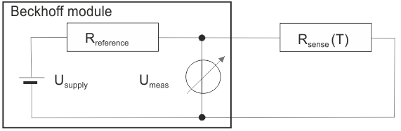 Fig.27: Circuit diagram for direct resistance measurement
Terminal families
- EL320x:
- Terminals switchable for operation in 2/3/4-wire technology (depending on version)
- EL321x:
- Terminals preferred for operation in 3-wire technology
- Operation in 2-wire technology is possible depending on the version (see information in the technical data), but is not recommended due to the lower measuring accuracy (see IO Analog Manual, chapter Connection techniques and supply line resistance compensation).
Additional notes
- Special characteristic curves that are not included in the CoE transformations, e. g. Pt375, can be acquired via the freely parameterizable EL3204-0200
- Due to the measuring principle, an RTD sensor may not be connected in parallel to several input channels.
- To improve measuring accuracy, the empirically determined supply line resistance in the CoE can be made known to the firmware in two-wire mode.
- Connection of resistance sensors
- EL32xx: in the range 0... 4096 Ω
- EL3204-0200: up to 240 kΩ
- EL3692: 0...10 Ω
The EL3692 is recommended for measurements in the range 0...10 Ω, since the measuring range of 1 or 4 kΩ is only poorly utilized with the EL32xx terminals and the measurement uncertainty (specified in %FSV) becomes relatively high - Additional transition resistances are to be expected with the ES32xx connector variants. In case of doubt, the EL32xx variant is preferable.
- Resolution
- Default setting: temperature measurement in 1 digit = 0.1°C
- Increased resolution: 1 digit = 0.01°C
The resolution is increased purely computationally in the firmware, the ADC resolution does not increase. Measured value jumps of > 0.01°C are to be expected. - For resistance measurement
- 1/64 Ω (0 Ω... 1024 Ω)
- 1/16 Ω (0 Ω... 4096 Ω)
Notes on connection in two-wire operation and on characteristic curves of KT/KTY sensors
Terminals | For operation with two-wire technology | Characteristic curves for KT/KTY sensors |
|---|---|---|
EL3201-xxxx | the +R and +RL inputs must be bridged by the user. |
|
EL3202-xxxx | ||
EL3204 | - | |
EL3214 | the +R and +RL inputs must be bridged by the user. | - |
EL3218 | the sensor must be connected between +R and -R without an external bridge to RL. | - |