Data stream and measurement ranges
Table of contents |
|---|
• Data stream |
Data stream
The flow chart at the bottom (Fig. Data stream representation of the EL31xx) illustrates the data stream in the EL31xx (processing of the raw data).
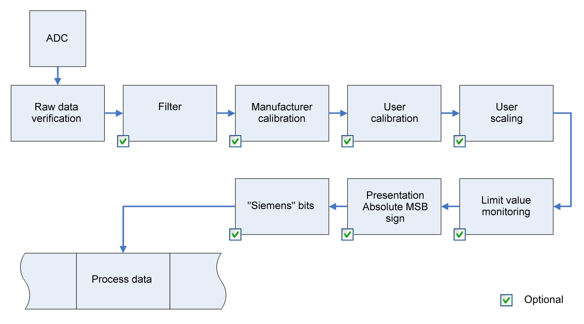 Fig.235: Data stream representation of the EL31xx
Calculation of process data
The concept “calibration”, which has historical roots at Beckhoff, is used here even if it has nothing to do with the deviation statements of a calibration certificate. Actually, this is a description of the vendor or customer calibration data/adjustment data used by the device during operation in order to maintain the assured measuring accuracy.
The terminal constantly records measured values and saves the raw values from its A/D converter in the ADC raw value object 0x80nE:01. After each recording of the analog signal, the correction calculation takes place with the vendor and user calibration data as well as the user scaling, if these are activated (see fig. Data stream representation of the EL31xx).
Calculation | Designation |
|---|---|
XF = f(XADC) | Output value after the filter |
YH = (XADC – BH) x AH x 2-14 | Measured value after vendor calibration, |
YA = (YH – BA) x AA x 2 -14 | Measured value after vendor and user calibration |
YS= YA x AS x 2-16 + BS | Measured value following user scaling |
Name | Designation | Index |
|---|---|---|
XADC | Output value of the A/D converter | |
XF | Output value after the filter | - |
BH | Vendor calibration offset (not changeable) | |
AH | Vendor calibration gain (not changeable) | |
BA | User calibration offset (can be activated via index 0x80n0:0A) | |
AA | User calibration gain (can be activated via index 0x80n0:0A) | |
BS | User scaling offset (can be activated via index 0x80n0:01) | |
AS | User scaling gain (can be activated via index 0x80n0:01) | |
YS | Process data for controller | - |
 | Measurement result The accuracy of the result may be reduced if the measured value is smaller than 32767 / 4 due to one or more multiplications. |
Measurement ranges
The diagrams at the bottom show the output values of the measurement ranges and the behavior if the limit ranges are exceeded.
EL310x, EL3112-0011, EL3142-0010
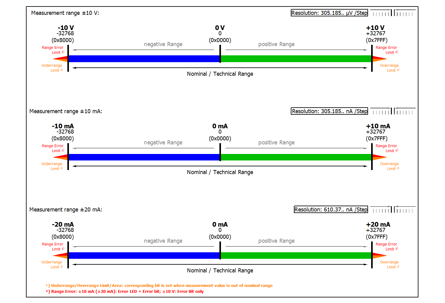 Fig.236: Measurement ranges ± 10 V, ± 10 mA and ± 20 mA (applicable as given by ‘X’ by the following table)
Terminal | Measurement range | ||
|---|---|---|---|
± 10 V | ± 10 mA | ± 20 mA | |
EL310x | X | - | - |
EL3112-0011 | - | - | X |
EL3142-0010 | - | X | - |
EL311x, EL314x
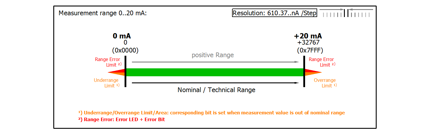 Fig.237: Measurement range 0...20 mA
EL312x, EL315x
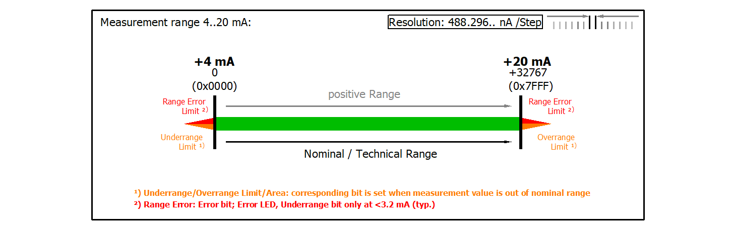 Fig.238: Measurement range 4...20 mA
EL316x
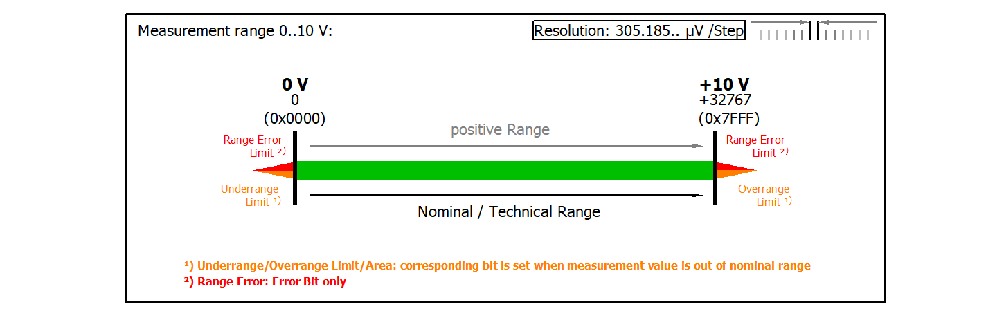 Fig.239: Measurement range 0...10 V
EL3174, EL3174-00xx scaler: extended range/ legacy range
The EL3174 or the EL3174-00xx terminal respectively has the scaler (AI Advanced settings Object 0x80nD:12) “Extended Range” default set. This type of scaling allows an exceeding of the positive or negative value of approx. 7%. The technical useable range is within -107% to +107% of the respective full scale value. Example: the full scale value is ±10 V, so the technical range is -10.7 V to +10.7 V. The Legacy Range however provides the conventional range from -100% to +100% (e.g. usable range -10 V to +10 V) and +100% correspond to +32767 (-100% to -32768).
For the Extended Range 100% of a 16 bit PDO value ±30518 (0x7736) have been defined. Therefore resulting is the meaning of a bit given by the (user selected measurement range) respective full scale value (FSV) as follows:

Diagrams of all measurement ranges are shown as follows:
Measurement range ±10 V (bipole):
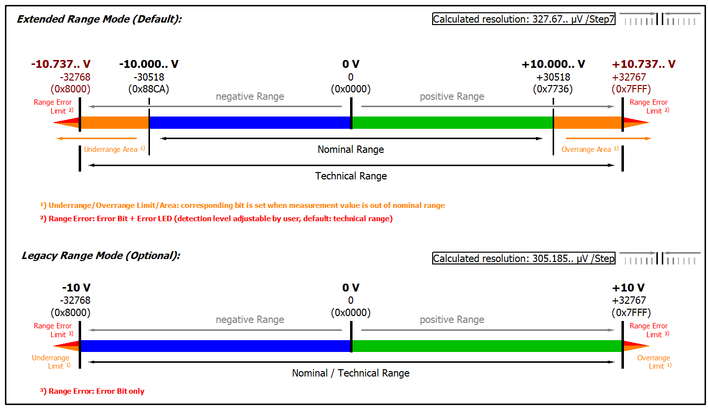 Fig.240: EL3172, EL3174, EL3174-0002, EL3174-0090: measurement range -10…+10 V
Measurement range ±3 V (bipole):
 Fig.241: EL3174-0032: measurement range -3…+3 V
Measurement range ±30 V (bipole):
 Fig.242: EL3174-0042: measurement range -30…+30 V
Measurement range ±60 V (bipole):
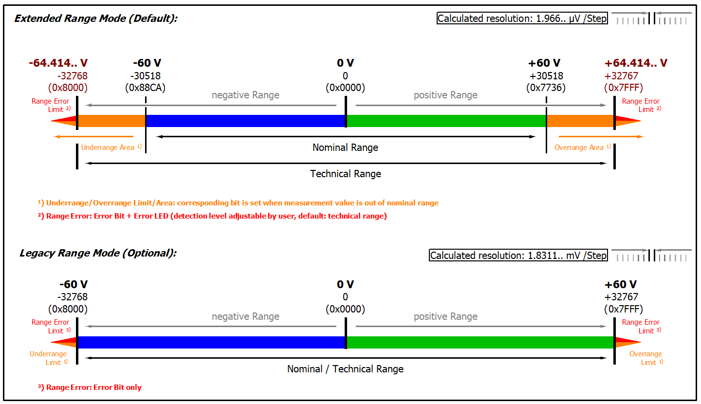 Fig.243: EL3174-0042: measurement range -60…+60 V
Measurement range 0…10 V (unipole):
 Fig.244: EL3172, EL3174, EL3174-0002, EL3174-0090: measurement range 0…10 V
Measurement range 0…3 V (unipole):
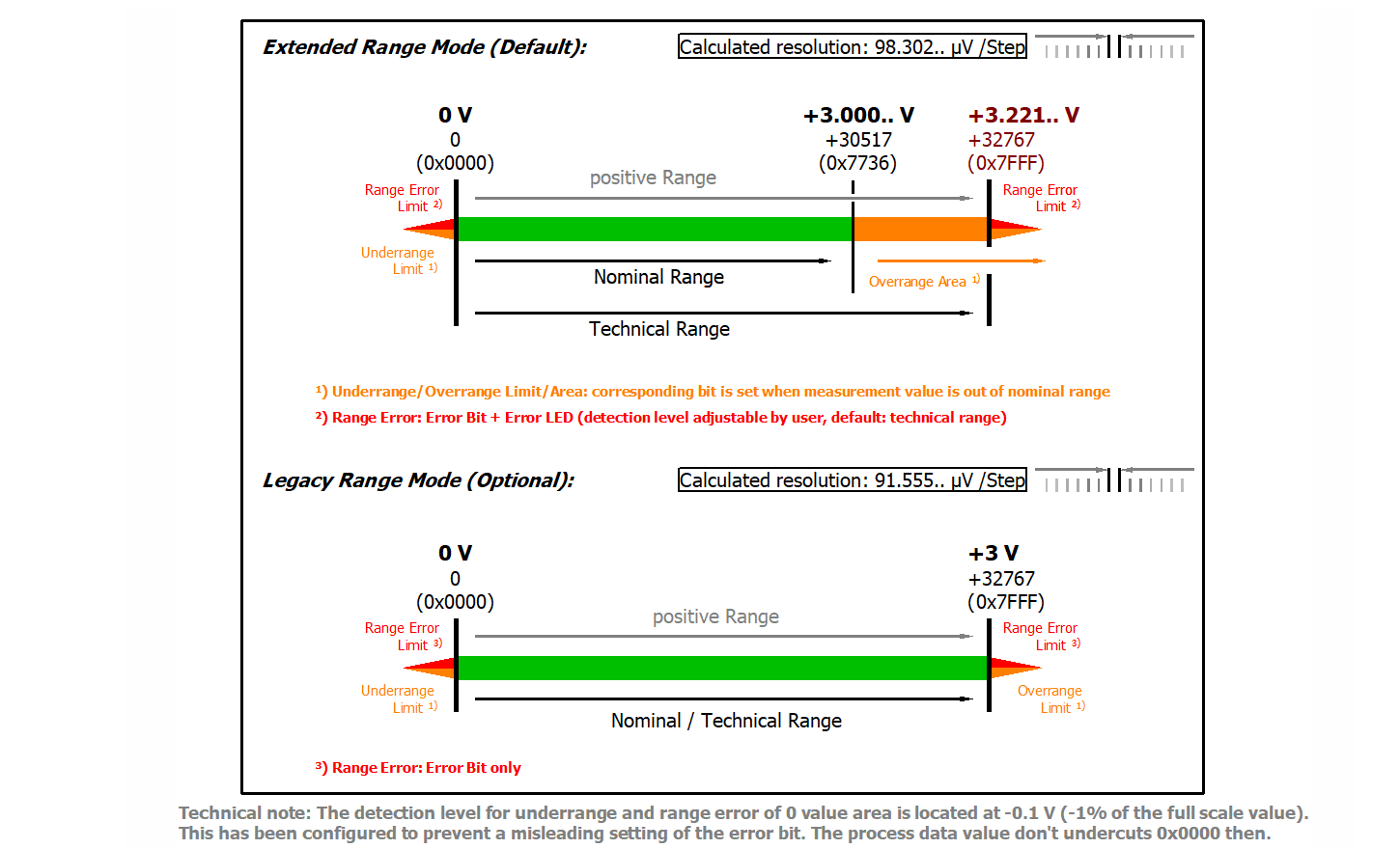 Fig.245: EL3174-0032: measurement range 0…3 V
Measurement range ±20 mA (bipole):
 Fig.246: EL3172, EL3174, EL3174-00xx: measurement range -20…+20 mA
Measurement range 0...20 mA (current loop):
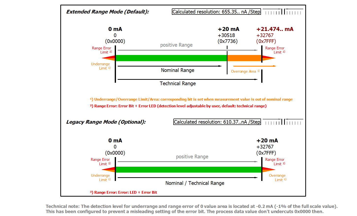 Fig.247: EL3172, EL3174, EL3174-00xx: measurement range 0…20 mA
Measurement range 4...20 mA (current loop):
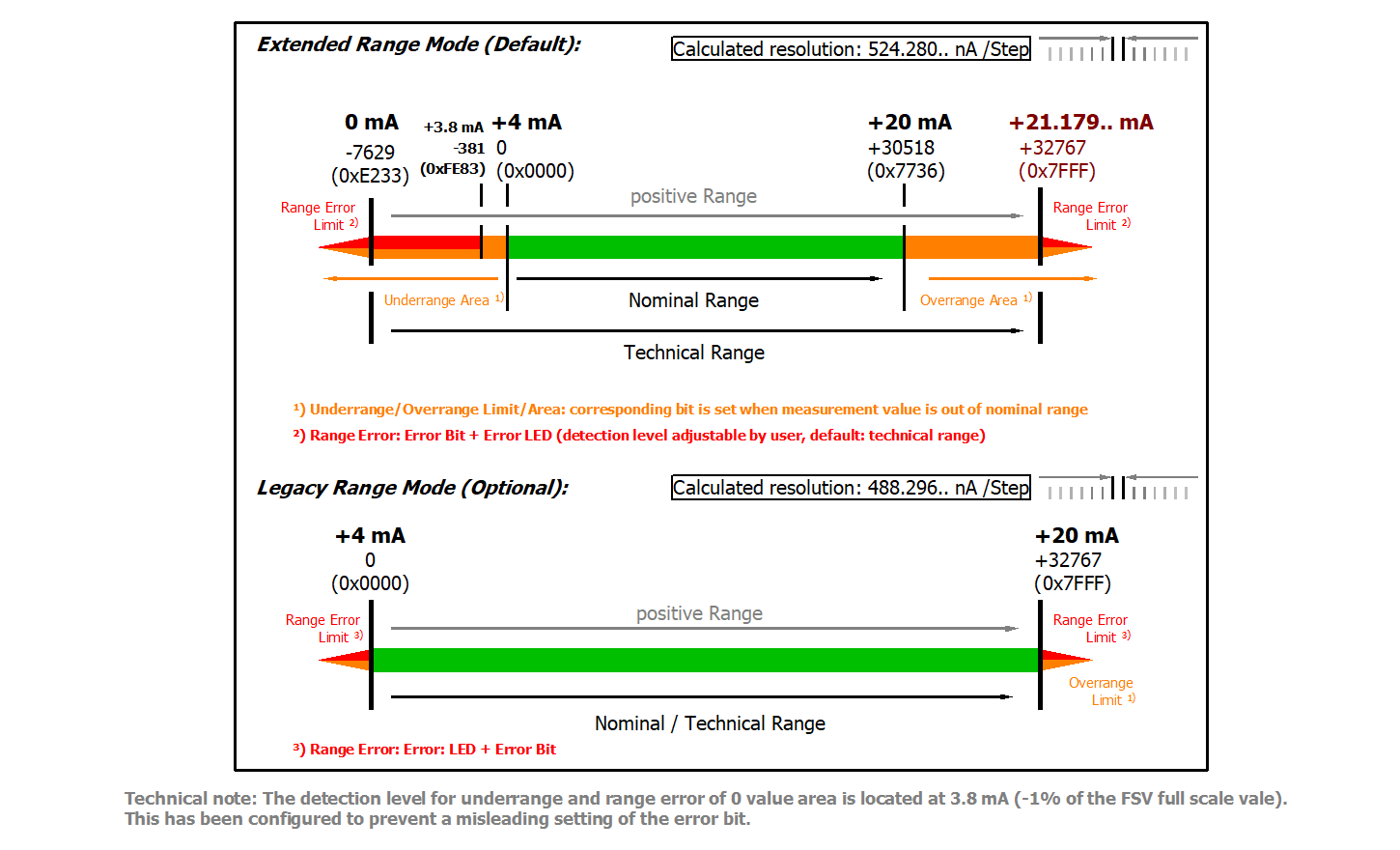 Fig.248: EL3172, EL3174, EL3174-00xx: measurement range 4…20 mA
Measurement range 4...20 mA/ NAMUR NE43 (current loop):
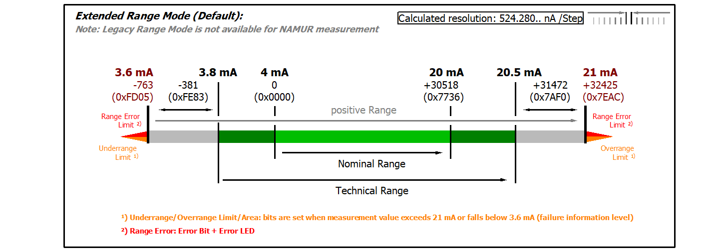 Fig.249: EL3172, EL3174, EL3174-00xx: measurement range 4…20 mA (NAMUR NE43)
Calibration
Vendor calibration, index 0x80n0:0B
The vendor calibration is enabled via index 0x80n0:0B. Parameterization takes place via the indices
User calibration, index 0x80n0:0A
The user calibration is enabled via index 0x80n0:0A. Parameterization takes place via the indices