Commissioning
- 1. Input voltage in index 0x8000:03 “Supply voltage” in the unit 0.01 V
- 2. Set the operation mode in the CoE directory in index 0x8004:01 to “Current Control trigger pulse”
- 3. Set Predefined PDO Assignments to "External trigger input (with info data)"
- 4. Set the parameters for the LED output (if used):
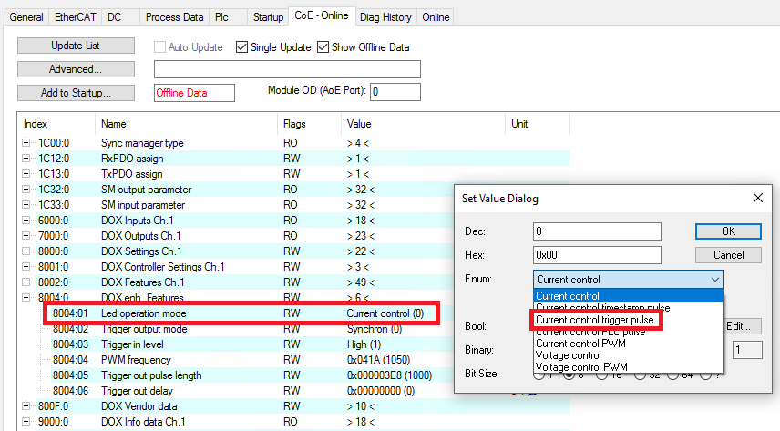 Fig.159: Operation mode setting “Current control trigger pulse”
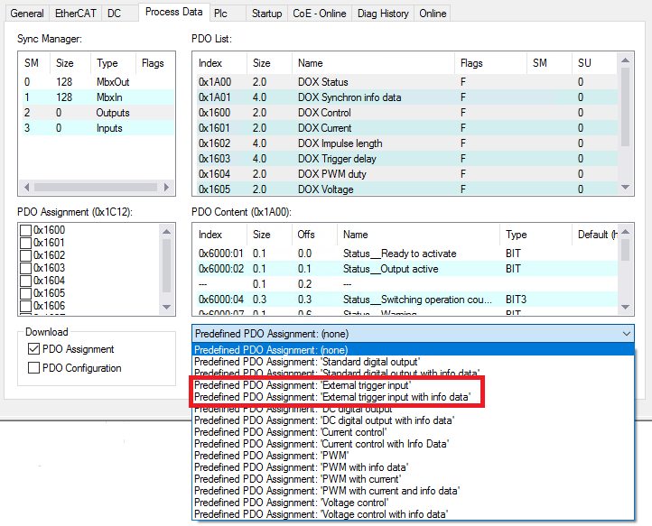 Fig.160: PDO setting “External trigger pulse (with info data)”
- Specify the output current in the unit mA via “DOX Current” → “Output current”
- Specify the pulse length in the unit µs via “DOX Impulse length” → “Impulse length”. The resolution of the time can be reduced from 1 µs to 100 ns using the CoE index 0x8002:31 “Pulse resolution 100 ns”.
- Specify the pulse delay in the unit µs via “DOX Trigger delay” → “Trigger delay”. The resolution of the time can be reduced from 1 µs to 100 ns using the CoE index 0x8002:31 “Pulse resolution 100 ns”. Alternatively, the delay can be firmly specified in the unit 0.1 µs in the CoE index 0x8000:0B
- 5. Select the trigger mode for the trigger output in CoE index 0x8004:02
- If the LED output and the trigger output are to be used, any trigger mode can be selected, except for the “Standard output” mode.
- If only the trigger output is to be used in response to the trigger input, only the trigger modes “Synchron”, “Synchron inverted”, “Synchron pulse with separate trigger delay” and “Synchron pulse inverted with separate trigger delay” can be used.
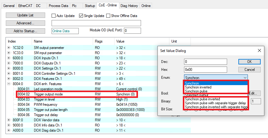 Fig.209: Setting the trigger mode
- 6. Setting the specific settings for the trigger mode
Trigger mode | Description | Settings |
|---|---|---|
Synchron | Trigger output TRUE if LED output is TRUE | The PDO values for the LED output are adopted for delay and pulse length
|
Synchron inverted | Trigger output TRUE if LED output is FALSE | |
Synchron pulse | Trigger output has at the same time a rising edge like the LED output | The PDO value for the LED output is adopted for the delay
The separate pulse length for the trigger output is set in the CoE
|
Synchron pulse inverted | Trigger output has a falling edge when the LED output has a rising edge | |
Synchron pulse with separate trigger delay | Trigger output has a rising edge with a specified delay when the LED output has a rising edge | The separate delay and pulse length for the trigger output are set in the CoE |
Synchron pulse inverted with separate trigger delay | Trigger output has a falling edge with a specified delay when the LED output has a rising edge |
- 7. In the CoE index 0x8002:30, set whether the LED pulse should be generated by a rising or falling edge at the trigger input.
- 8. In the CoE index 0x8004:03, specify the level at the trigger input at which the LED output should be switched (high ≥ 10 V, low ≥ 5 V).
- 9. Connect the trigger signal to the TrigIn+ (5) and TrigIn- (13) connections
- 10. Activate the trigger input under “DOX Control” → “Control” → “Input Trigger Enable”
- 11. Connect the device to be controlled (e.g. camera) to the TrigOut trigger output (2)
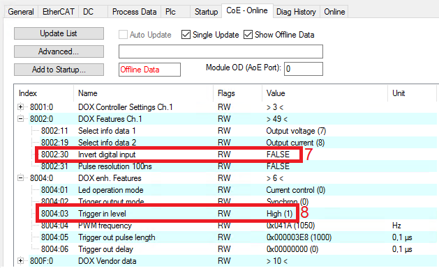 Fig.210: Settings in the CoE objects for the combination of trigger input and output
 - The external device to be controlled via the trigger output can be supplied with power via TrigOut+ (3) and TrigOut- (4).
- An external voltage divider can be connected to the TrigExtDiv contacts (10, 11, 12) to reduce the supply voltage for the device in use (see Connection of trigger output)
- 12. Activate the trigger output under “DOX Control” → “Control” → “Output Trigger Enable”
- 13. Check under “DOX Status” → “Status” whether the “Ready to activate” bit is 1.
- 14. Activate the control under “DOX Control” → “Control” via the “Enable” bit.
- 15. Switch on the output under “DOX Control” → “Control” by activating the “Output” bit