Connection to the trigger output
The EL2596-xxxx has a trigger output for triggering a camera. This trigger output can be switched on in every pulse mode (Current control PLC pulse, Current control timestamp pulse and Current control trigger pulse).
The supply UTrigOutSupply for the trigger function between 10 V and 24 V is to be connected from outside to TrigOut+ and TrigOut-. The trigger input of the camera with its required voltage U1 is connected
- to TrigOut if U1 = UTrigOutSupply and can thus be switched directly through, or
- to TrigExtDiv (see diagram of external voltage dividers) if U1 < UTrigOutSupply (e.g. for 5 V) and therefore has to be divided down
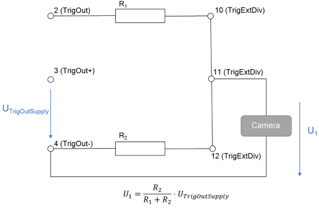 Fig.203: Voltage divider for the trigger output
When dimensioning the resistors of the voltage divider R1 and R2, make sure that R1 + R2 > 2 kΩ. With lower resistances, the power loss at the resistors would be high and would lead to strong heating.