Commissioning of the trigger output
The following steps are necessary in order to set the trigger output:
- Set “DOX Control” → “Control” → “Output Trigger Enable” to 1
- Select the trigger mode in the CoE index 0x8004:02
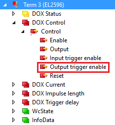 Fig.204: Activate the output trigger
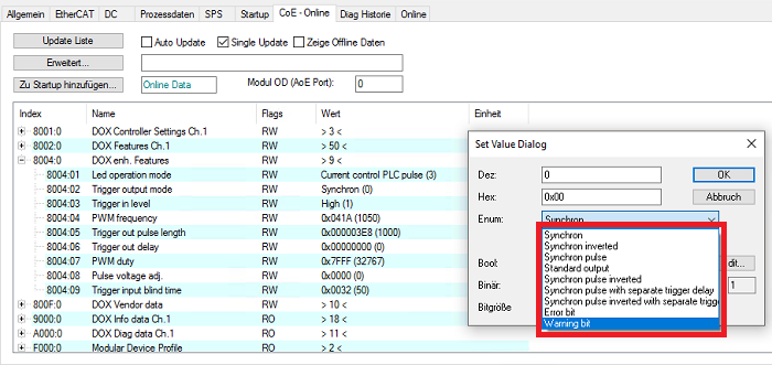 Fig.205: Select the trigger mode in the CoE index 0x8004:02
Element | Name | Description |
|---|---|---|
0 | Synchron | The trigger output is triggered when the LED output is TRUE. |
1 | Synchron inverted | The trigger output is triggered when the LED output is FALSE. |
2 | Synchron pulse | The trigger output is triggered if the LED output has a rising edge The pulse duration of the trigger output is set in 0.1 µs via the index 0x8004:05. |
3 | Standard output | The trigger output can be used in the PLC as a digital output, independent of the LED output. This trigger mode is independent of the set LED output mode. The output can be set via the bit “Output trigger enable” (“DOX Control” → “Control” → “Output trigger enable”). |
4 | Synchron pulse inverted | The trigger output is triggered if the LED output has a falling edge. The pulse duration of the trigger output is set in 0.1 µs via the index 0x8004:05. |
5 | Synchron pulse with separate trigger delay | If the LED output has a rising edge, the trigger output is triggered with a specified delay. The delay for the trigger output is specified in the unit µs in the PDO 0x1607. If it is not mapped, the delay must be specified in 0.1 µs in the index 0x8004:06. The pulse duration of the trigger output is set in 0.1 µs via the index 0x8004:05. |
6 | Synchron pulse inverted with separate trigger delay | If the LED output has a falling edge, the trigger output is triggered with a specified delay. The delay for the trigger output is specified in the unit µs in the PDO 0x1607. If it is not mapped, the delay must be specified in 0.1 µs in the index 0x8004:06. The pulse duration of the trigger output is set in 0.1 µs via the index 0x8004:05. |
7 | Error bit | The trigger output is TRUE as long as there is an error of the EL2596 (supply/output voltage outside the value specified in the indices 0x8000:12, 0x8000:14, 0x800:16, overtemperature, wire breakage, ...) |
8 | Warning bit | The trigger output is TRUE as long as there is a warning of the EL2596 (supply/output voltage outside the value specified in the indices 0x8000:11, 0x8000:13, 0x800:15, overtemperature, ...) |
The timing behavior of the trigger modes 0, 1, 2, 4, 5 and 6 with the output bit and the trigger output is shown in the following figure.
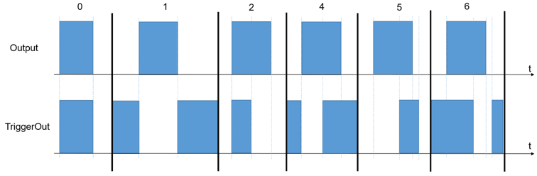 Fig.206: Timing at the trigger output
In addition to the PDO values for the delay and pulse length, the EL2596 has a specific delay and a specific pulse length for the trigger output. These specific values in the CoE indices (0x8004:05 “Trigger out pulse length”, 0x8004:06 “Trigger out delay”) can only be used if “Trigger output mode” “Synchron pulse with separate trigger delay” (5) or “Synchron pulse inverted with separate trigger delay” (5) is enabled in the CoE index 0x8004:02. For all other set trigger modes in the CoE index 0x8004:02, the values from the PDOs “Output length” and “Trigger delay” are used, or the delay value from the CoE index 0x8000:0B is used, which are also valid for the LED output. In any case, the values from the PDOs or the delay value from the CoE index 0x8000:0B are used for the LED output.