Time behavior
The trigger output can also be used in combination with the trigger input. A signal at the trigger input can then enable both the LED output and the trigger output. There are various ways in which trigger inputs (TriggerIn), LED output (LED Out) and trigger output (TriggerOut) are combined with one another. Four possibilities of temporal behavior are shown in the following illustration. The various options are described below.
In addition to an edge at the trigger input, the TriggerIn signal can also correspond to a signal from the PLC (PLC Pulse) or a specified start time of the distributed clocks (DC Pulse).
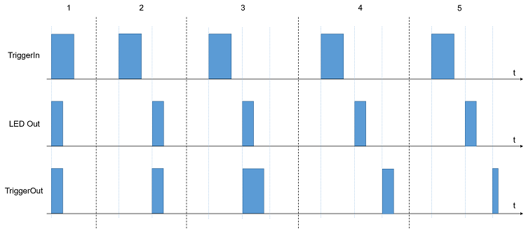 Fig.210: Time behavior when combining trigger input and trigger output
- With a rising edge at the trigger input, the LED output and the trigger output switch synchronously to the trigger input. Both outputs have the same pulse length.
- The LED output and the trigger output have a uniform delay with respect to the rising edge at the trigger input. Both outputs (LED Out, TriggerOut) switch synchronously with the same pulse length.
- The LED output and the trigger output have a uniform delay with respect to the rising edge at the trigger input. Both outputs (LED Out, TriggerOut) switch synchronously with different pulse lengths.
- The LED output and the trigger output have delays with respect to the rising edge at the trigger input. However, the delays are configured differently for both outputs, so that the outputs do not switch synchronously. Both outputs have the same pulse length.
- The LED output and the trigger output have delays with respect to the rising edge at the trigger input. However, the delays are configured differently for both outputs, so that the outputs do not switch synchronously. The outputs have different pulse lengths.
In the parameterization, it is therefore possible to set the different delays for the LED output, as well as the trigger output, as well as to set the pulse lengths of the two output signals independently of each other.
However, it should be noted that the delay between the trigger input and the trigger output cannot be zero due to internal factors in the terminal. There is always a delay of about 2 µs between the trigger input and the trigger output. This basic delay of 2 µs acts as an offset to the set delay. The offset of 2 µs must also be observed for all set delay values (regardless of whether they are set via PDO or CoE). The resulting delay is always

The basic delay described is visible in the following figure. In addition, the output at the trigger output has a jitter of ±500 ns, with the maximum of +500 ns occurring only rarely.
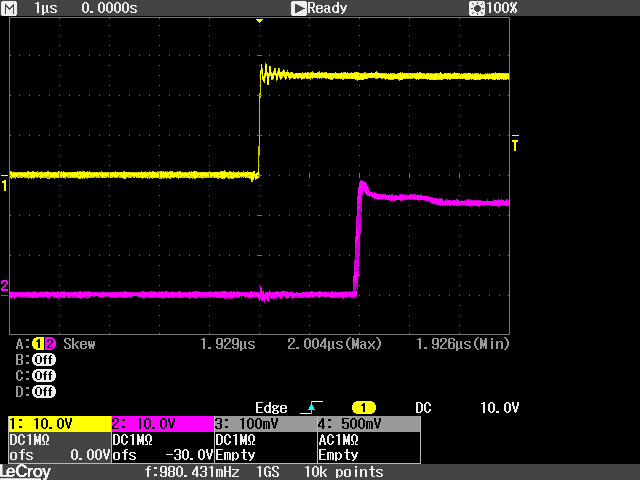 Fig.211: Basic delay between trigger input and trigger output
The yellow signal (Channel 1) shows the input trigger. This signal is generated by an EL2202. In order to achieve reliable, reproducible behavior at the trigger output, it is imperative to use a signal with steep edges at the trigger input. The purple signal (Channel 2) shows the trigger output. The trigger output is parameterized so that the set delay of the trigger output is zero. Due to the basic delay described above, a delay in the range of 1.9 µs to 2.0 µs is set.
The commissioning procedure is described below:
- Limit current in index 0x8000:02 “Target current” in the unit mA
- Input voltage in index 0x8000:03 “Supply voltage” in the unit 0.01 V
- Desired output voltage in index 0x8000:04 “Output voltage” in the unit 0.01 V
- Set the operation mode in the CoE directory in index 0x8004:01 to “Current Control trigger pulse”
- Set Predefined PDO Assignments to “External trigger input (with info data)”
- Pulse length of the LED output (and the trigger output) specified via “DOX Impulse length” → “Impulse length” in the unit µs. The resolution of the time can be reduced from 1 µs to 100 ns using the CoE index 0x8002:31 Pulse resolution 100 ns.
- If you want to specify your own pulse length for the trigger output, “Trigger output mode”, “Synchron pulse with separate trigger delay” (5) or “Synchron pulse inverted with separate trigger delay” (6) must be enabled in the CoE index 0x8004:20.
- Only if 7. has been executed: A separate pulse length for the trigger output can then be specified via the CoE index 0x8004:05 “Trigger out impulse length”.
- Specify the delay of the LED output (and the output trigger) with respect to the trigger signal via “DOX Trigger delay” → “Trigger delay” in the unit µs. The resolution of the time can be reduced from 1 µs to 100 ns using the CoE index 0x8002:31 Pulse resolution 100 ns. Alternatively, the delay can be firmly specified in the unit 0.1 µs in the CoE index 0x8000:0B.
- Only if a delay for the trigger output is to be specified and 7. has been executed: A separate delay for the trigger output can then be specified via CoE index 0x8004:06 “Trigger out delay” or via PDO 0x1607 “Trigger out delay”.
- In the CoE index 0x8002:30, specify whether the LED pulse should be generated by a rising or falling edge at the trigger input
- In the CoE index 0x8004:03, specify the level at the trigger input at which the LED output should be switched (high ≥ 10 V, low ≥ 5 V)
- Connect the trigger signal to the TrigIn+ (5) and TrigIn- (13) connections
- Activate the trigger input under “DOX Control” → “Control” → “Input Trigger Enable”
- Connect the device to be controlled (e.g. camera) to the TrigOut trigger output (2). The external device to be controlled via the trigger output can be supplied with power via TrigOut+ (3) and TrigOut- (4). An external voltage divider can be connected to the TrigExtDiv contacts (10, 11, 12) to reduce the supply voltage for the device in use.
- Activate the trigger output under “DOX Control” → “Control” → “Output Trigger Enable”
- Check under “DOX Status” → “Status” whether the “Ready to activate” bit is 1
- Activate the control under “DOX Control” → “Control” via the “Enable” bit
- Switch on the output under “DOX Control” → “Control” by activating the “Output” bit