Voltage Control PWM
The operation mode “Voltage Control PWM” enables an LED to be driven by pulse width modulation of the voltage.
In this mode, the voltage is set to the value specified in the CoE index 0x8000:04 “Output voltage”. The output current depends on the connected load. The output current can increase to 200% of the “Target current” (limit current) in the CoE index 0x8000:02. If the resistance of the connected load is too low, so that the output current would have to rise to more than 200% of the set limit current in order to keep the output voltage constant at the specified value, the terminal switches the output off.
In this operation mode, it is possible to configure the trigger input as an enable input so that it can be used as an external switch. An output can then only be actuated with a prespecified signal at the trigger input. More detailed information and commissioning can be found in the chapter Hardware enable.
The specific parameters for setting the LED output as a voltage-PWM-controlled output are described below.
- Nominal/limit current of the LED in index 0x8000:02 “Target current” in the unit mA
- Input voltage in index 0x8000:03 “Supply voltage” in the unit 0.01 V
- Desired output voltage in index 0x8000:04 “Output voltage” in the unit 0.01 V (max. UIN - 2 V).
- The default PWM frequency is 1050 Hz. If necessary, the value can be adjusted in index 0x8004:04.
WARNING
- Set the operation mode in the CoE directory in index 0x8004:01 to “Voltage Control PWM”
- Set Predefined PDO Assignments to “PWM (with info data)”
- Specify PWM duty cycle under “DOX PWM duty” → “PWM duty”. If the PDO object 0x1604 “DOX PWM duty” is not mapped, the duty cycle is specified in the CoE index 0x8004:07.
- Check under “DOX Status” → “Status” whether the “Ready to activate” bit is 1.
- Activate the control under “DOX Control” → “Control” via the “Enable” bit.
- Switch on the LED output under “DOX Control” → “Control” by activating the “Output” bit.
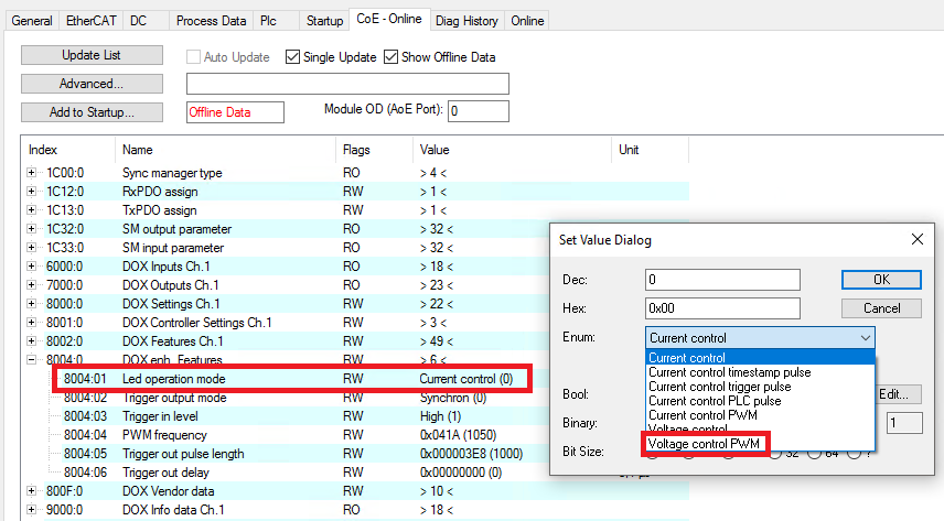 Fig.176: Operation mode setting “Voltage control PWM”
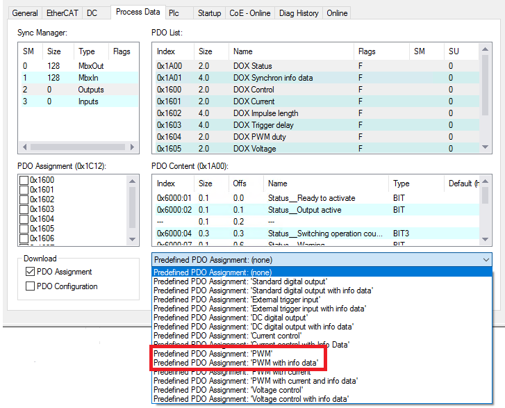 Fig.169: PDO setting “PWM (with info data)”
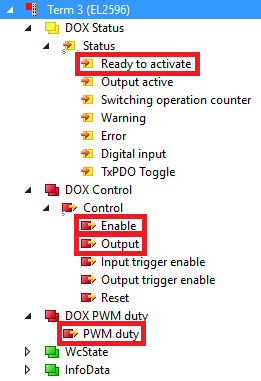 Fig.172: Activating the output in the operation mode “Voltage control PWM”