Current control
It is possible to use the LED output as a digital or current-controlled LED output via the selection of the Predefined PDOs.
In this mode the maximum output current is 1.2 A up to an LED voltage of 12 V. Above 12 V the user must consider derating, as otherwise the module may switch off due to overtemperature if the power exceeds 14.4 W.
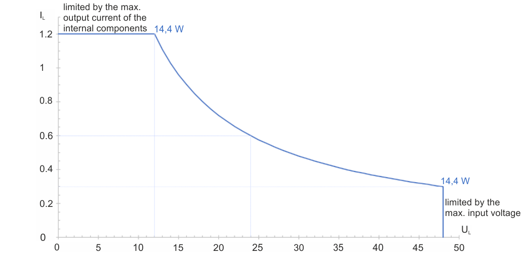 Fig.141: Operating range of EL2596 in "Current control" mode
If an LED is to be operated with an nominal current Inominal < 10 mA, the Current Control PWM mode should be used.
In this operation mode, it is possible to configure the trigger input as an enable input so that it can be used as an external switch. An output can then only be actuated with a specified signal at the trigger input. More detailed information and commissioning can be found in the chapter Hardware enable.
Current-controlled LED output
Make the following settings:
- Nominal/limit current of the LED in the unit mA in the CoE parameter 0x8000:02 “Target current”
- Input voltage in the unit 0.01 V in the CoE parameter 0x8000:03 “Supply voltage”
- Maximum output voltage in the unit 0.01 V (max. UIN - 0.5 V) in the CoE parameter 0x8000:04 “Output voltage”. In this mode, the controller outputs only the forward voltage required for the set forward current. Nevertheless, the forward voltage should still be specified for the desired LED current in order to protect the connected LED from overvoltage. The TeachIn function can also be used to determine the output voltage.
- Set the operation mode to “Current control” in the CoE directory in the parameter 0x8004:01
- Under “Predefined PDO Assignments”, set “Current control (with info data)”.
- Specify the set current in the unit mA via “DOX Current” → “Output Current”
- Check under “DOX Status” → “Status” whether the “Ready to activate” bit is 1.
- Activate the control under “DOX Control” → “Control” via the “Enable” bit.
- Switch on the LED output under “DOX Control” → “Control” by activating the “Output” bit.
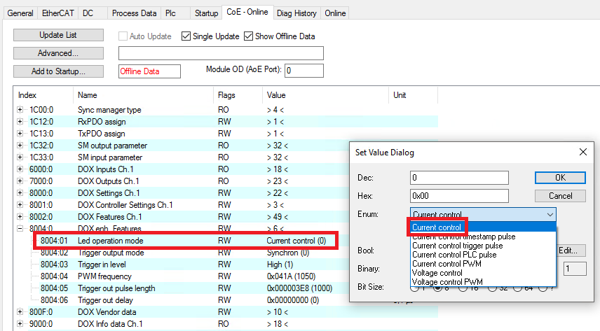 Fig.148: Operation mode setting “Current control”
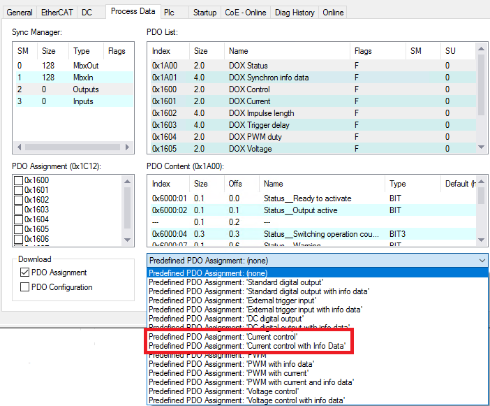 Fig.149: PDO setting “Current Control (with info data)”
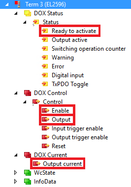 Fig.150: Activate the output in the operation mode “Current control”
Digital current output
Make the following settings:
- Output current in the unit mA in the CoE parameter 0x8000:02 “Target current”
- Input voltage in the unit 0.01 V in the CoE parameter 0x8000:03 “Supply voltage”
- Desired output voltage in the unit 0.01 V (max. UIN - 0.5 V) in the CoE parameter 0x8000:04 “Output voltage”
- Set the operation mode in the CoE directory in the parameter 0x8004:01 to “Current Control”
- Set the “Predefined PDO Assignments” to “Standard digital output (with info data)”.
- Check under “DOX Status” → “Status” whether the “Ready to activate” bit is 1.
- Activate the control under “DOX Control” → “Control” via the “Enable” bit.
- Switch on the LED output under “DOX Control” → “Control” by activating the “Output” bit.
Fig.148: Operation mode setting “Current Control”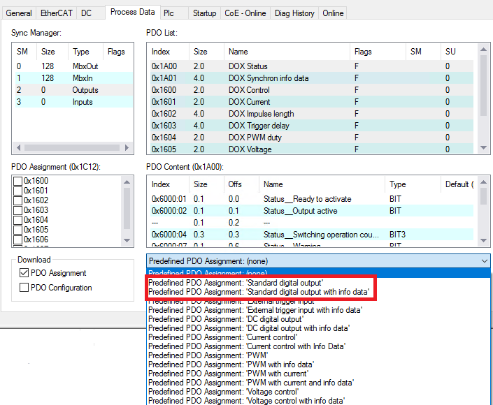 Fig.152: PDO setting “Standard digital output (with info data)”
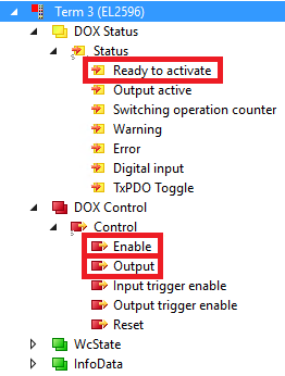 Fig.153: Activate the output in operation mode “Current Control” as a digital output