Basic function
The EL2502 has three basic operation modes with additional settings for each channel. These are accessed via the PDO selection.
- "Pulse width (standard)":
- Duty cycle specification via process data (cyclic)
- Frequency specification via CoE (acyclic)
The operation mode for each channel is set via CoE object 0x80n0:07 (channel 1: n = 0, channel 2: n = 1)
This mode is to be used if only the duty cycle is to be changed quickly in the real-time context.
Operating range | Note | CoE 0x80n0:07 | Period value from CoE | Period unit | Permissible value range | Frequency range |
|---|---|---|---|---|---|---|
PWM 20 Hz .. 20 kHz |
| 0 | [1000 ns = 1 µs] | 80 .. 32657 (signed) | 20 Hz .. 20 kHz | |
PWM 100 ns frequ. resolution |
| 2 | [100 ns] |
| 153 Hz .. 125 kHz | |
PWM 1 Hz .. 20 kHz | from firmware 07, Rev. EL2502-0000-0019 | 3 | [1000 ns = 1 µs] |
| 1 Hz .. 20 kHz |
The corresponding output frequency can be calculated from the period.
Note on the "100 ns" operation mode: a value < 80 [*100 ns] corresponding to 125 kHz cannot be processed. If such an invalid value is entered in the CoE, the terminal has to be started in PREOP state, so that the CoE entry can be corrected in this state.
- "Pulse width and frequency (16*bit)", (from firmware 02, Revision EL2502-0000-0017)
- Duty cycle specification via process data (cyclic)
- Frequency setting [20 Hz .. 20 kHz] via process data 16-bit unsigned (cyclic), 1 digit = 1 µs period
This mode is to be used if the duty cycle and the frequency are to be quickly changed in the real-time context.
Operating range | Note | CoE 0x80n0:07 | Period value from | Period unit | Permissible value range | Frequency range |
|---|---|---|---|---|---|---|
PWM 20 Hz |
| not relevant | Process data | [1000 ns = 1 µs] | 0 .. 65535 (unsigned only) | 20 Hz .. 20 kHz (typ. 17 .. 21 kHz) |
- "Pulse width and frequency 1 Hz (32-bit)", (from firmware 08, Revision EL2502-0000-0021)
- Duty cycle specification via process data (cyclic)
- Frequency setting [1 Hz .. 20 kHz] via process data 32-bit unsigned (cyclic), 1 digit = 1 µs
This mode is to be used if the duty cycle and the frequency are to be quickly changed in the real-time context. The frequency can be reduced to 1 Hz.
Operating range | Note | CoE 0x80n0:07 | Period value from | Period unit | Permissible value range | Frequency range |
|---|---|---|---|---|---|---|
PWM 1 Hz .. 20 kHz | from firmware 08, Rev. EL2502-0000-0021 | not relevant | Process data | [1000 ns = 1 µs] | 0 .. 1000000 | 1 Hz .. 20 kHz |
The basic setting is made via the PDO(process data) selection in the ProcessData tab. This can be done
- via the Predefined PDO Assignment (from ESI revision EL2502-0000-0020), see Fig. Operation mode selection (B)
- via the individual selection of the PDO, Fig. Operation mode selection (A)
"Pulse width": PDO 0x1600 and 0x1601
"Pulse width and frequency (16 bits)": PDO 0x1602 and 0x1603
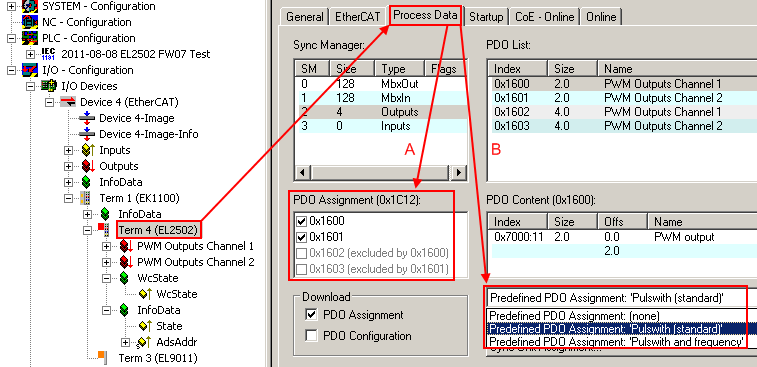 Fig.135: Operation mode selection
The parameters are considered in the following order:
 Fig.136: EL2502 data flow diagram