Example 2: Multi-time stamping
The following example program uses 10-fold multi-time stamping in which a set of 10 (set) switching states are transferred together with the associated different switching times to the process data of the EL2212 terminal. So that the required process data are available for linking to the program variables, multi-time stamping 10x must be selected on the Process Data tab.
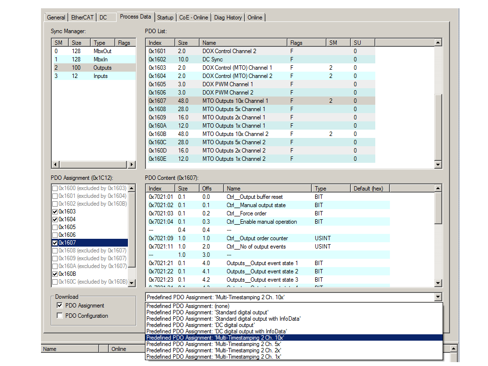 Fig.188: Selection of predefined process data via the "Process_Data" tab: Multi-time stamping 2 ch. 10x
In addition, Distributed Clock must be used and is selected via the "DC" tab:
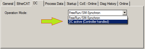 Fig.189: Activation of DC
The settings in the "DOX Settings" object for channel 1 (Index 0x8000) are to be made as follows:
- Supply voltage: 60 V
- Holding current: 600 mA
- Coil resistance: 25 Ω
- "Boost current" of the switch-on phase: 1200 mA (initially still inactive)
- Current switch off threshold: -300 mA (initially still inactive)
- "Booster on time " of the switch-on phase: 5 ms
- "Booster off time " of the switch-on phase: 5 ms
The current switch-off threshold should be set to "TRUE"; it takes effect as soon as the overexcitation is activated in the switch-off phase "Boost-Off" and in this way prevents in advance a possible overstressing of mechanical components.
 Fig.190: CoE object 0x8000 configuration for 24 V valve control
Energization of a pneumatic valve 24 V, 600 mA
The setup already used in Application Demonstration 2 is used again here: a pneumatic valve with a holding current of 600 mA and alternating current flow is energized with the following 10 switching times (in ms): [1, 50, 25, 75, 25, 50, 75, 50, 25, 50]. The first switching state is "1" with the switching time 1 ms in order to generate the first rising edge without delay from the PLC for the beginning of the switching phases. In the illustrations below this edge was used to trigger the oscilloscope for the oscilloscope recordings. The valve is connected to channel 1 of the terminal.
Oscilloscope channel assignment:
- Channel 1: current flow in converted 400 mA / division
- Channel 4: setpoint value of the control
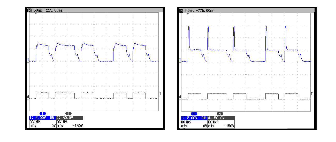 Fig.191: Current flow (1) and setpoint switching value (4): left without overexcitation, holding current 600 mA; right with overexcitation "Boost-On" 10 ms/1200 mA and holding current 400 mA
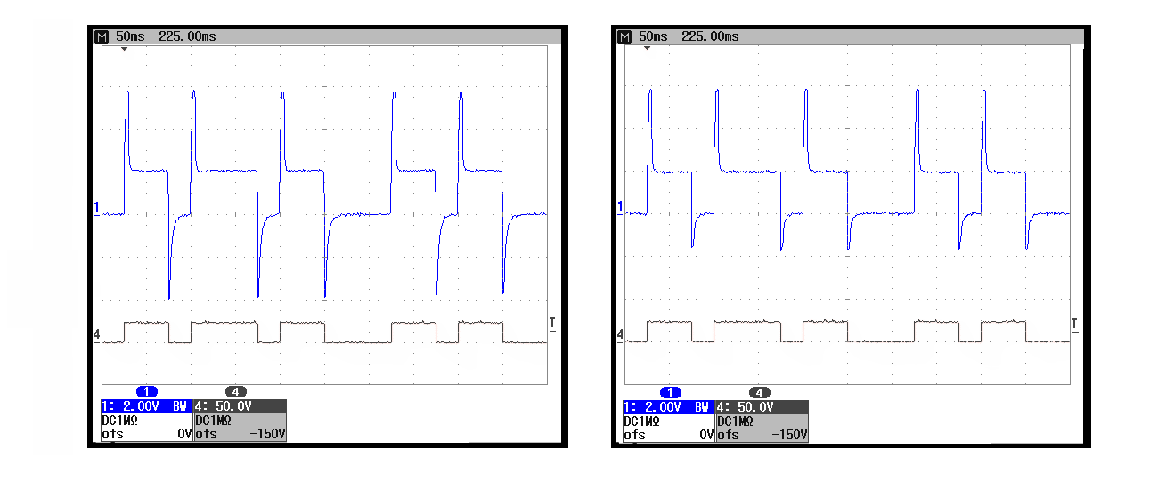 Fig.192: Current flow (1) and setpoint switching value (4): left with overexcitation "Boost-On" 10 ms/1200 mA and Boost-Off 10 ms; additionally with activated current switch-off threshold – left set to -550 mA, right set to -300 mA
 Energization of a relay 24 V, 200 mA
For comparison, two oscilloscope recordings of a relay with switching times (in ms) of [100, 200, 250, 100, 150, 200, 100, 150, 200, 150] are shown in the following. The holding current and the overexcitation current have been set in advance to 200 mA and 400 mA respectively in the CoE object "DOX Settings Ch. 1". With the first switching state "1" and the associated first switching time 100 ms from the PLC, the first rising edge is generated again for the trigger.
Oscilloscope channel assignment:
- Channel 1: current flow in converted 200 mA / division
- Channel 2: NC contact of the relay
- Channel 3: NO contact of the relay
- Channel 4: setpoint value of the control
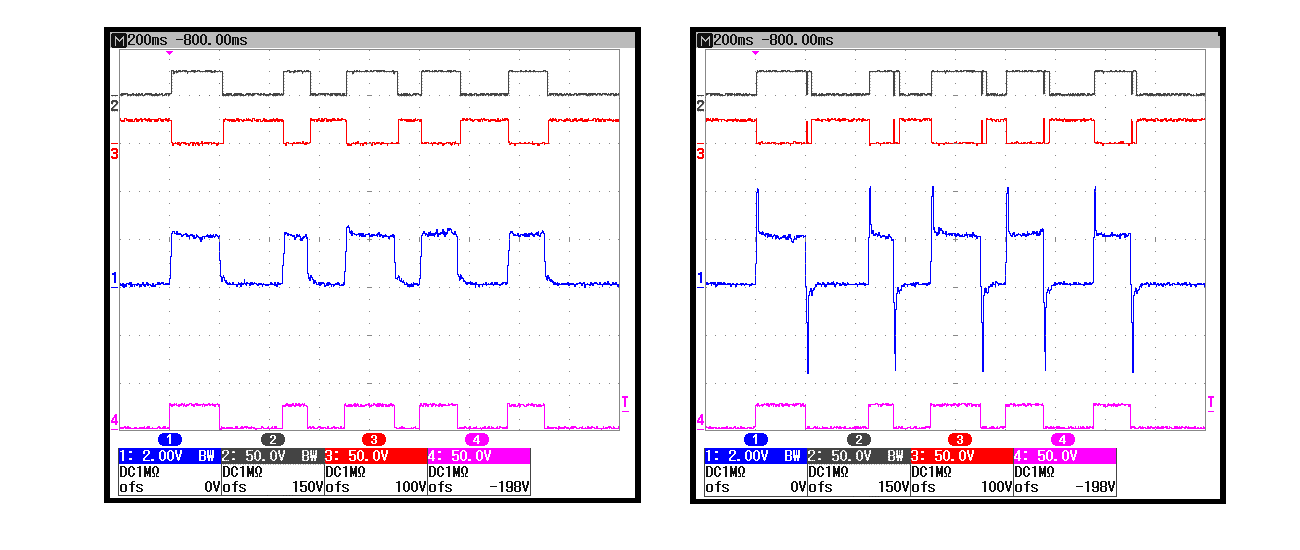 Fig.193: Recording with the oscilloscope: energization of a relay with multi-time stamping
The bouncing of the NC and NO contacts already known from Application Demonstration 1 can be seen in the right-hand oscillogram; this bouncing is caused by an excessively high reverse current from the overexcitation of the switch-off phase – the "Boost-Off" in the control coil – and thus an excessively fast switch-off.
Program to example 2
All arrays have to be linked to a channel with all the necessary status, output and input variables respectively. This is already be done by the downloadable example:
Download: Program
You can use either an embedded PC that has the terminal placed on the right or an IPC with an EtherCAT link of an e.g. RJ‑45 connector to the EK1100 coupler with the terminal (e.g. C6915 + EK1100 + EL9190 + EL2212). Optionally a digital input terminal e.g. EL1004 can be set before the EL9190 for program control. A relay is connected instead of a valve and the coil resistance have to be set in CoE Object DOX Settings (0x8000:05) respectively.
Variables declaration:
PROGRAM MAINVAR_INPUT // External switch to start by user bEnable AT%I* : BOOL; // To check if last tasks were already executed bReadyToActivate AT%I* : BOOL; // Target state given back by the EL2212 (Feedback) bOutputState AT%I* : BOOL;END_VARVAR_OUTPUT // Reference signal for e.g. trigger of oscilloscope bOutputReference AT%Q* : BOOL; // Link to terminal EL2212 (Output event time n): aQE_Time AT%Q* : ARRAY[0..9] OF UDINT; // Link to terminal EL2212 (Output event state n): aQE_State AT%Q* : ARRAY[0..9] OF BOOL; // Outputvariables to reset the output-buffers of EL2212 bOutputBufReset AT%Q* : BOOL; // Real number of fixed State/Time-Events as a Task for EL2212 nNoOfOutputEvents AT%Q* : USINT; // Start-Event to trigger beginning of task scheduling nOutputOrderCnt AT%Q* : USINT;END_VARVAR aSwitchTime : ARRAY[0..9] OF UDINT:= // All 10 time offsets in ms allocated to the 10 states: [ 100, 200, 250, 100, 150, 200, 100, 150, 200, 150 ]; nState : UINT:=0; // Use for "CASE .. OF" statement nShortTime : ULINT; // Timevalue of current DC time/ lower 32 Bit only nCurrentTime : ULINT; // Current DC-Time of the PLC-Task bStateValue : BOOL; // Variable to set a toggled state of a task-event nScheduleNo: INT; // Consists No of respective state/time pair // of a Switch-TaskEND_VARProgram:
// Example program 2: 10x Multi-Timestamp for EL2212nCurrentTime := F_GetCurDcTaskTime64(); // Get current DC-Time (Task-Related)// Overtake feedback of EL2212 to any output terminal// for using as trigger / reference signal:bOutputReference := bOutputState;CASE nState OF// ====================== Do some initializations here: ============================0:// Reset ouput buffer of the terminal EL2212 bOutputBufReset := TRUE; nState := nState + 1;// Go to next state1: bOutputBufReset := FALSE; nState := nState + 1; // Go to next state2:// Wait for external start-event by user (e.g. ext. switch) IF bEnable THEN nState := 10; // Go to next state and set events END_IF// =================================================================================// ============ Now fill up all state/time pairs for the four channels =============10:// Last tasks already executed? IF bReadyToActivate THEN bStateValue:=1; // Set first state level ('1') aQE_State[0] := bStateValue; // Cut 64 Bit time value to 32 Bit nShortTime := nCurrentTime AND 16#FFFFFFFF; // Set first time value (duration for "save" begin) aQE_Time[0] := (ULINT_TO_UDINT(nShortTime) + aSwitchTime[0] * 1000000); // Use 'nScheduleNo' as loop counter FOR nScheduleNo:=1 TO 9 DO bStateValue := NOT bStateValue; // Set inverting output states of one switch-task aQE_State[nScheduleNo] := bStateValue; // Set timestamps of one switch-task aQE_Time[nScheduleNo] := (aQE_Time[nScheduleNo-1] + aSwitchTime[nScheduleNo] * 1000000); END_FOR nState := nState + 1; // Go to next state END_IF// =================================================================================// ======== Allow some taskcycles (min. 2) to let EL2212 schedule all tasks ========11: // 'nScheduleNo' is still 9; wait until 12: 3 more PLC-Taskcycles IF nScheduleNo = 12 THEN nNoOfOutputEvents := 10; // Trigger Multi-Timestamp scheduling: now start: nOutputOrderCnt := nOutputOrderCnt + 1; nState := nState + 1; ELSE // Just count PLC-Taskcycles here nScheduleNo := nScheduleNo + 1; END_IF12:// ================================== End ========================================== // Wait for external switch to be released IF NOT bEnable THEN nState := 0; // Go to beginning state END_IFEND_CASEPreparations for starting the sample programs (tnzip file / TwinCAT 3)
- Click on the download button to save the Zip archive locally on your hard disk, then unzip the *.tnzip archive file in a temporary folder.
- Select the .tnzip file (sample program).
- A further selection window opens. Select the destination directory for storing the project.
- For a description of the general PLC commissioning procedure and starting the program please refer to the terminal documentation or the EtherCAT system documentation.
 Fig.194: Opening the *. tnzip archive
- The EtherCAT device of the example should usually be declared your present system. After selection of the EtherCAT device in the “Solutionexplorer” select the “Adapter” tab and click on “Search...”:
- Checking NetId: the “EtherCAT” tab of the EtherCAT device shows the configured NetId:
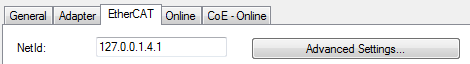 .
.
The first four numbers must be identical with the project NetId of the target system. The project NetId can be viewed within the TwinCAT environment above, where a pull down menu can be opened to choose a target system (by clicking right in the text field). The number blocks are placed in brackets there next to each computer name of a target system. - Modify the NetId: By right clicking on “EtherCAT device” within the solution explorer a context menu opens where “Change NetId...” have to be selected. The first four numbers of the NetId of the target computer must be entered; both last values are 4.1 usually.
Example: - NetId of project: myComputer (123.45.67.89.1.1)
- Entry via „Change NetId...“: 123.45.67.89.4.1
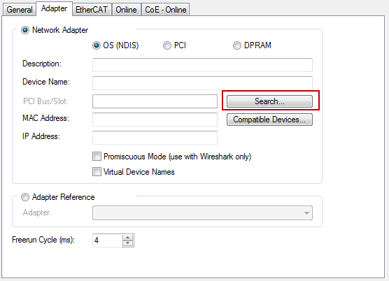 Fig.195: Search of the existing HW configuration for the EtherCAT configuration of the example
Also see more hints in section:
Commissioning, TwinCAT Quickstart, TwinCAT 3, Startup.
Assignment of the process data and settings
 | EL2212: "DC" tab – selection of the DC operating mode The operating mode "DC active (controller handled)" must be set for the functional capability of this program. |
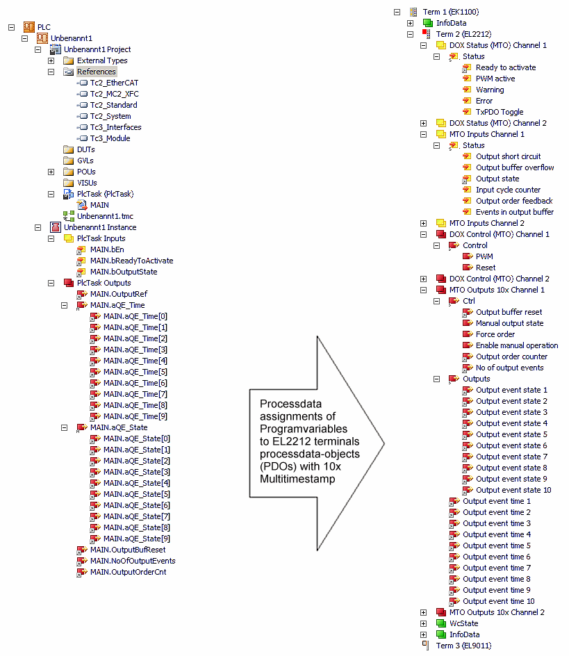 Fig.196: Matching of the external variables from "Main" to the multi-time stamping PDOs