Application demonstration 2: 24 V pneumatic valve
A fast-switching pneumatic valve with a rated voltage of 24 V and an internal resistance of 25 Ω is operated here. It is switched on vie PLC 20 ms.
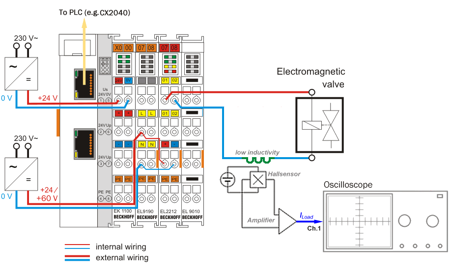 Fig.171: Setup for Application Demonstration 2
For this illustration a rated current of 600 mA is defined for switching the valve. The following illustrations each show on the left-hand side the recording of the current curve with the oscilloscope (converted 400 mA/div) and on the right-hand side the associated settings in the CoE objects Configuration data, DOX Settings and DOX Features. The following are entered:
- Holding current: 600 mA
- Supply voltage: 24 V
- Winding resistance: 25 Ω
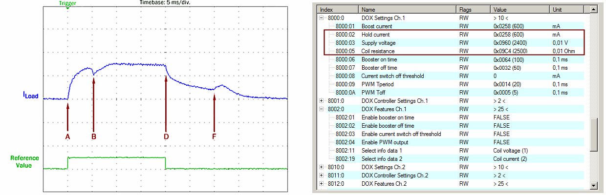 Fig.172: Exemplary current curve ILoad with 24 V supply voltage, normal operation of the EL2212
The markings in the oscilloscope recording A to D show the switching on/off of the valve with 24 V. The armature needs approx. 5 ms (A to B) until it is excited and the air gap is closed. The excitation current (Iload) of nominal 600 mA is also maintained during the holding phase until D.
Explanation of the oscilloscope recording:
A: Switch-on of the output, start of the switch-on phase
B: Excitation of the armature
D: Switch-off of the output (end of the switch-on phase)
F: Release of the armature
The winding current decreases slowly after the output (D) is switched off. The time of the mechanical release of the valve armature, recognizable by the current curve (F) rising again, provides information about the required switch-off time of similarly about 10 ms (tD to tF).
1. The holding phase is configured with a low holding current
The following are entered by direct CoE access via the TwinCAT user interface:
- Holding current: 400 mA
- Boost current (switch-on phase): 600 mA
- Booster on time: 10 ms
subsequently the overexcitation of the switch-on phase "Boost On" is activated.
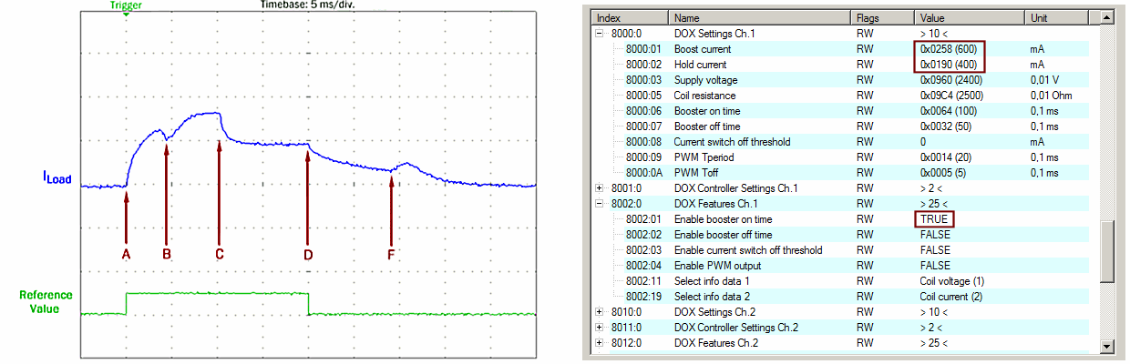 Fig.173: Regulation of the reduced holding current after mark C: end of overexcitation in the switch-on phase
Following the "Boost on time" (tA to tC) of the switch-on phase, the EL2212 terminal's internal PWM controller begins to reduce the holding current from 600 mA to 400 mA. Over the further course, the PLC program switches the output off again (after the remaining 10 ms) later (tC to tD). Due to the reduced holding current the armature is also released a little earlier, as can be seen by the decrease in the time tF by about 1 ms.
2. Activation of overexcitation for accelerated switching
In order to increase the dynamics, 60 V is now applied for a short period to the 24 V valve. A double rated current value of 1200 mA during the overexcitation time is additionally configured in the CoE. The changes done by CoE are as follows:
- Supply voltage: 60 V
- "Boost on current" of the switch-on phase: 1200 mA
Since the valve armature now requires only approx. 2 ms to be excited instead of 5 ms (marking from A to B), it was possible to shorten the overexcitation time accordingly:
- "Booster on time " of the switch-on phase: 5 ms
The result is then as shown below:
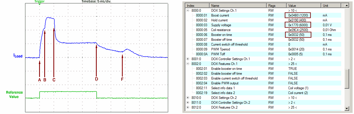 Fig.174: Current curve ILoad with a supply voltage of 60 V and overexcitation of 1200 mA/5 ms.
After mark C, the end of the overexcitation in the switch-on phase, the EL2212 regulates the holding current back to 400 mA until the conventional switch-off (D).
3. Activation of the accelerated switch-off
In order to accelerate the release of the armature, the valve coil is "impressed" with a reverse voltage of 60 V. The switch-off current threshold is configured and activated as a precaution, since unforeseen damage to mechanical components could occur. The current is internally evaluated by the EL2212 and leads to premature switching off of the reverse current. The CoE entries are to be made as follows:
- Current switch off threshold: 100 mA
- "Booster off time" on: 10 ms
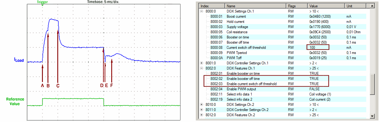 Fig.175: Current curve ILoad: overexcitation "on" with 1200 mA/5 ms, "off" 5 ms and current switch-off threshold +100 mA
In the oscilloscope recording, mark E shows the end of the overexcitation in the switch-off phase "Booster off time". At mark E the preset switching threshold of +100 mA is already reached about 0.5 ms after switching off the output (D) and the overexcitation for the switch-off – the "Boost-Off" phase – is thus ended. The period from tD to tF corresponds to the accelerated switch-off of the valve of just 3 ms compared to the original 10 ms.
Summary of the results
|
Operation |
Switch-on phase |
Switch-off phase |
|---|---|---|
|
conventional |
approx. 5 ms |
approx. 10 ms |
|
with boost-on/boost-off overexcitation |
approx. 2 ms |
approx. 3 ms |
|
Improvement |
approx. 60% |
approx. 66% |
The acceleration achieved already lies well within the range of usual PLC cycle times. Taking into account appropriately by means of sensors or test, the application can execute individual process steps with shorter cycle times.
By way of example, the current curves for two further different current switch-off thresholds in the over-excited switch-off phase are shown in the following:
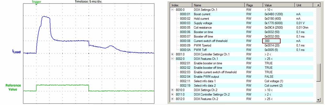 Fig.176: Exemplary current curve ILoad with over-excited switch-on and switch-off phase, current switch-off threshold +300 mA
 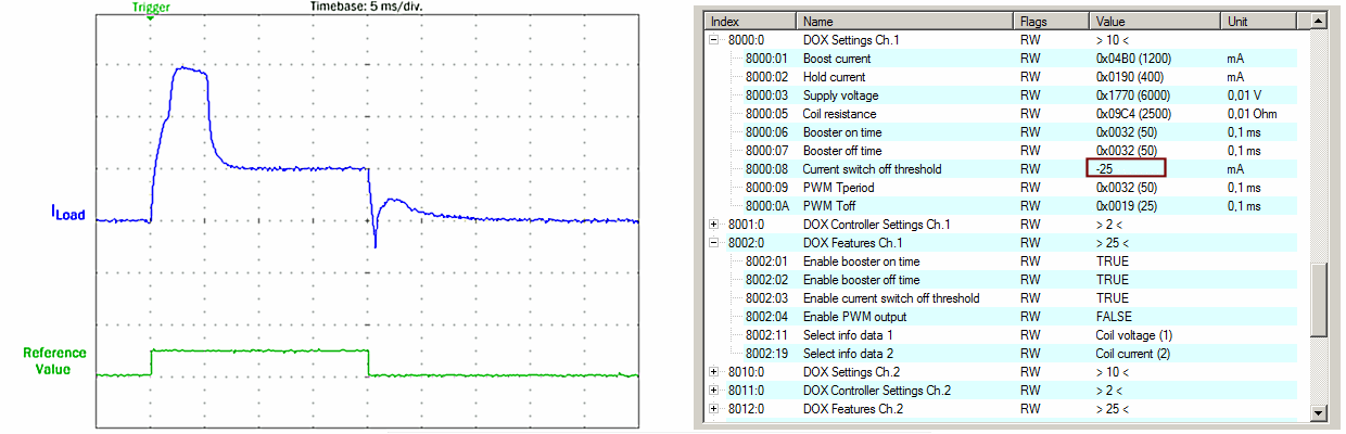 Fig.177: Exemplary current curve ILoad with over-excited switch-on and switch-off phase, current switch-off threshold -25 mA
The larger the current switch-off threshold, the shorter the switch-off time:
With a current switch-off threshold of -25 mA, the switch-off phase is shortened by up to approx. 2 ms. It is obvious that this setting has a considerable influence on the wear of mechanical components; in particular, damage should be avoided and the current switch-off threshold therefore be selected with particular care.
In the following the over-excited switch-off phase – the Boost-Off – is deactivated again and the external PWM is activated with a duty factor of 2.5 ms/5 ms, i.e. 50% and the current curve is recorded:
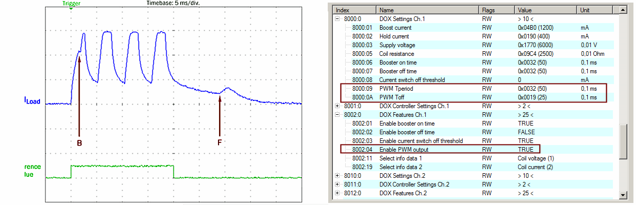 Fig.178: Exemplary current curve ILoad with over-excited switch-on phase and PWM with 50% duty factor
The excitation and release of the valve armature is recognizable as before by the saddle points of the current curve (B and F). Since the inductivity is not large enough to properly smooth the current at this PWM frequency (200 Hz), however, the individual pulses are recognizable in the current curve. Nevertheless, the valve armature remains in place until F in this example, since the mechanical inertia of the valve construction sufficiently damps such an excitation.