Distributed Clocks settings
Basic principles
The EL2212 has a special feature in DC mode: usually the DC unit in the ESC is managed by the EtherCAT master. In the case of the EL2212, however, the local controller manages the start time and sets appropriate values in the ESC.
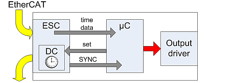 Fig.162: EL2212 DC schematic
The controller (B) receives timestamps, activation and target states as normal process data from the ESC (A). It parameterizes the ESC to the next start time. At the set time the ESC informs the controller of this via the SYNC signal and the controller then activates the output stages accordingly.
For this reason the corresponding DC entries cannot be changed in the TwinCAT System Manager despite DC mode, but the EL2212 can nevertheless be used as a ReferenceClock.
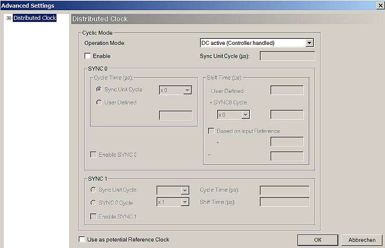 Fig.163: EL2212 DC settings
Determination of the current Distributed Clock time
If an up-to-date statement of the Distributed Clock time is needed in a PLC cycle, this can be linked via the input variable of the EtherCAT master.
 | Functions for data types with 64-bit width A selection of functions for handling 64-bit numbers is available under Beckhoff TwinCAT in the TcUtilities.lib library. Longer execution times are required here than is the case with standard, 32-bit data types. A data type with a width of 64 bit is defined in TcEthercat.lib as T_DCTIME or in TcUtilities.lib as T_LARGE_INTEGER. |
The EtherCAT master can display a copy of the current master distributed clock. To do this, activate the setting "Show DC System Time (64-bit)" in the EtherCAT device → EtherCAT tab → Advanced Settings → Distributed Clocks (see corresponding figure).
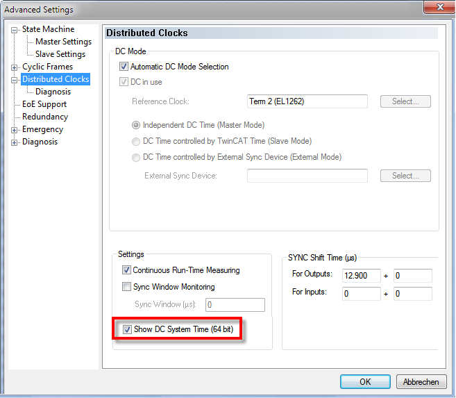 Fig.164: Activation of the master distributed clock display
The process image of the EtherCAT master now looks as shown in the figure below:
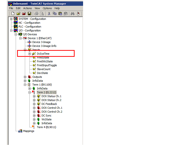 Fig.165: Extended process image of the EtherCAT master
 | SYSTIME The EtherCAT master value DcSysTime is to be used with care and should serve only as a coarse indication as to which time zone (order of magnitude: 1-2 task cycles) the Distributed Clocks system is currently in. |
Process data
For the operation of the EL2212 the activation of the process data provided for this is necessary.
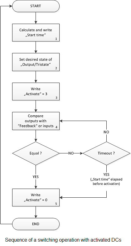
Example of a sequence with activated Distributed Clocks
The following sequence is to be adhered to when using the EL2212 with activated Distributed Clocks:
|
|
|
|
Therefore, only one switching event can be defined for each EL2212, which affects all 4 output variables Output and Tristate of channel 1 and 2 at the same time. For each EtherCAT cycle only one switching event can be defined. It is permissible to carry out the writing of the output data target output states, start time and Activate = 0 in the same EtherCAT cycle. | |