Detect counting direction
The terminal can be configured via Index 0x80n1:1C “Direction inversion hysteresis” as follows:
- Detect counting direction: A positive rotation direction is output as “0” and a negative rotation direction as “1” in the process data “Direction inversion detected” (0x60n2:13).
or
- Detect reversion of rotation: If a reversal in the direction of rotation is detected, this is reported in the process data “Direction inversion detected” (0x60n2:13). This function can also be used for standstill monitoring.
Detect counting direction
- Set the hysteresis via index 0x80n1:1C “Direction inversion hysteresis” = 0
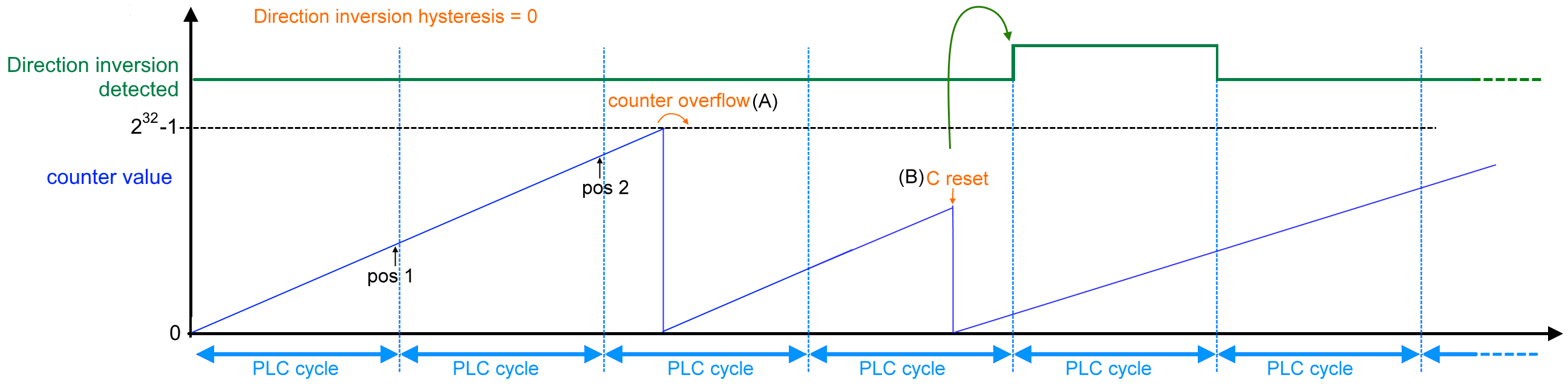
- To detect the counting direction, the position value of the last PLC cycle (pos 1) is subtracted from the position value of the current PLC cycle (pos 2).
- The result is output during the next PLC cycle via the process data “Direction inversion detected” (0x60n2:13). In this case,
- a positive result is interpreted as a positive direction of rotation
“Direction inversion detected” (0x60n2:13) = 0, - a negative result is interpreted as a negative direction of rotation
“Direction inversion detected” (0x60n2:13) = 1.
0x80n1:1C “Direction inversion hysteresis” = 0 | ||
|---|---|---|
Change in position | Direction of rotation | 0x60n2:13 “Direction inversion detected” |
pos 2 – pos 1 > 0 | Positive direction of rotation (CW) | 0 |
pos 2 – pos 1 < 0 | Negative direction of rotation (CCW) | 1 |
pos 2 – pos 1 = 0 | No change of direction of rotation | No state change |
Counter overflow | No change of direction of rotation | No state change |
Counter underflow | No change of direction of rotation | No state change |
- When the terminal is powered up, a positive direction of rotation is assumed in the first PLC cycle: “Direction inversion detected” (0x60n2:13) = 0,
because a second position value is initially missing for the calculation. - If an overflow “Counter overflow” (0x60n0:05) or underflow “Counter underflow” (0x60n0:04) of the counter value is detected, the result is corrected internally for the next PLC cycle. See figure (A) below.
- If the counter value is changed externally via the C track or the “Latch extern” input and this leads to a negative position jump, this is indicated via process data “Direction inversion detected” (0x60n2:13). See figure (B) below
- If reversion of rotation is enabled (index 0x80n0:0E “Reversion of rotation” = TRUE), the logic of the direction of rotation detection also changes.
Detect reversion of rotation
- Enter the hysteresis as the number of increments via the index 0x80n1:1C “Direction inversion hysteresis”. Select a value greater than 0.
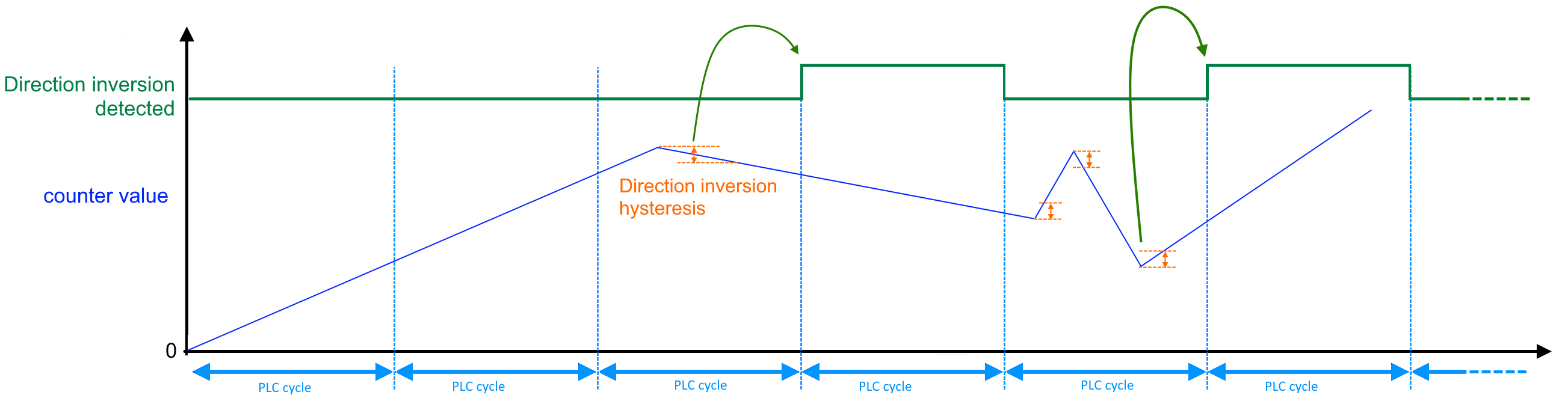
- If a direction inversion is detected, an internal counter evaluates the edges detected directly one after the other for each direction of rotation and compares them with the number entered in index 0x80n1:1C.
- If the counter value exceeds the value entered in index 0x80n1:1C, the bit in the process data “Direction inversion detected” (0x60n2:13) is set during the next PLC cycle. The bit remains active for one cycle only.
- The bit remains active if a further direction inversion is detected within the next cycle.
- The hysteresis is considered separately for each PLC cycle, so the counter is restarted for each cycle. There is no monitoring across PLC cycles.
- If reversion of rotation is enabled (index 0x80n0:0E “Reversion of rotation” = TRUE), the logic of the direction of rotation detection also changes.
- If several changes of direction occur within one PLC cycle, the display only indicates that at least one change of direction has been detected.
Standstill monitoring
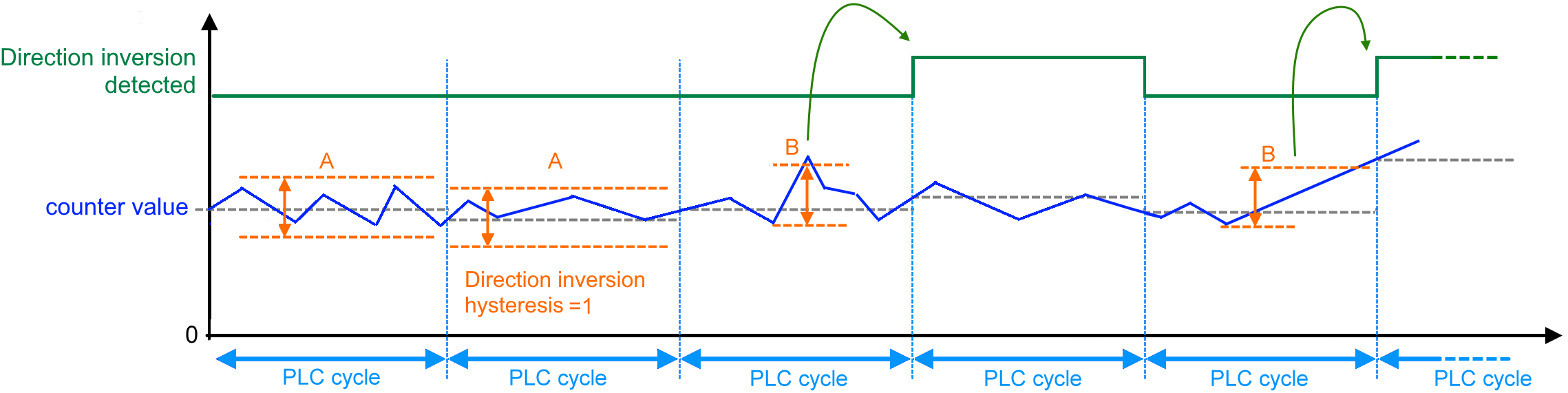
Detection of direction inversion can also be used for standstill monitoring. If an almost constant counter value is expected, the hysteresis (index 0x80n1:1C) can be used to monitor whether the value is within the window. A slight jitter of the counter value is therefore still accepted as a permissible value. If the limit is exceeded, the bit in the process data “Direction inversion detected” (0x60n2:13) is set during the next PLC cycle.
- If the direction changes again within the hysteresis [number of increments] specified in index 0x80n1:1C, no change of direction is indicated (standstill). See figure (A) below.
- If the hysteresis [number of increments] specified in index 0x80n1:1C is exceeded after a change of direction, the change of direction is indicated in the next cycle by setting the bit in the process data “Direction inversion detected” (0x60n2:13). See figure (B) below.
 | Drifting of the counter value Reliable detection of a drifting counter value can only be guaranteed if the value in index 0x80n1:1C “Direction inversion hysteresis” is “1”. Or additional monitoring of the counter value in the PLC. |