Reversion of rotation
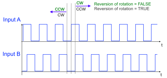
- With an encoder, the counting direction is determined by the phase position of the signals on tracks A and B.
- Forward (cw): Signal on track A leads track B by 90°
- Reverse (ccw): Signal on track A lags track B by 90°
To adapt the counting direction to the application, this logic can be inverted by setting the bit in index 0x80n0:0E “Reversion of rotation”.
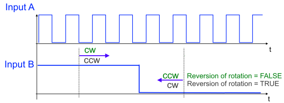
- With a counter/pulse generator the counting direction is determined by the level at track B.
- Forward (cw): LOW level at track B or input open
- Reverse (ccw): HIGH level at track B
Setting the bit in index 0x80n0:0E “Reversion of rotation” also inverts the logic of the counting direction. An overview of the resulting counting direction is shown in the following table.
The current level at input B is displayed via process data “Status of input B” (0x60n0:0A).
0x80n1:1D | Level at input track B | 0x80n0:0E | Resulting |
|---|---|---|---|
1: Counter RS422 | Input open / LOW level | FALSE | positive |
TRUE | negative | ||
RS422 signal level | FALSE | negative | |
TRUE | positive | ||
3: Counter TTL | Input open / LOW level, voltage level < 0.8 V | FALSE | positive |
TRUE | negative | ||
TTL voltage level | FALSE | negative | |
TRUE | positive | ||
5: Counter open collector | Input open / LOW level, voltage level < 0.8 V | FALSE | positive |
TRUE | negative | ||
Open collector voltage level | FALSE | negative | |
TRUE | positive |
 | Status LED input B as counter RS422 (diff. input) If the input of track B is open in counter mode “RS422 (diff. input)”, a broken wire is detected and the status LED of input B lights up red. The error detection and indication via the LED can be deactivated via index 0x80n0:0C “Error detection B”. |