Technology
As the most transparent port multiplier possible, the CU2508-0022 expands a Gigabit Ethernet port on the controller to eight Fast Ethernet ports in the field. It transports IEEE802.3 compliant Ethernet frames with arbitrary contents.
Application example

Each port of the CU2508-0022 sends and receives Fast Ethernet frames (100 Mbit, 100BASE-TX) via up to 100 m of copper cable. The CU2508-0022 does not generate any frames itself or process their content, but only forwards frames sent to it by a software driver via its 8 ports to the field or forwards frames received from the field to the driver. The highly precise time information regarding when the frames are sent or received is thereby optional.
The CU2508-0022 has the following ports for this purpose:
- An uplink port X09 (Gigabit Ethernet) to the driver in the controller, which requires at least one Gigabit Ethernet connection on the opposite side.
- Eight downlink ports X01-X08 (10/100 Mbit) for real-time traffic to the connected field devices.
A CU2508-0022 system therefore consists of the CU2508-0022 and the CU2508-0022 driver, integrated in TwinCAT.
The CU2508 system does not replace master implementations of Ethernet-based fieldbuses, but instead tunnels specified data telegrams via the gigabit connection and then sends the frames at the specified time. It behaves transparently for the protocols routed via it, with exception of the EtherCAT protocol – in this case a CU2508-0022 device is visible as the first slave in the configuration. Each materially existent I/O system on the field side must therefore match a logical master component in the controller.
Several CU2508-0022s can be used in each TwinCAT system.
Some sub-functions of the CU2508-0022 and operation modes are described below.
Properties of the downlink ports
The basic setting of the CU2508-0022 is optimized for use with EtherCAT downlinks, in particular for operation with EtherCAT cable redundancy.
In the event of a link loss on the uplink port, the link is retained on the downlink ports, but incoming frames are discarded.
ESL protocol
The software driver in the controller is the counterpart to the CU2508-0022. It works on a Gigabit Ethernet port in the controller and “packs” the user data into the EtherCAT Switch Link Protocol (ESL) or unpacks the ESL protocol from the CU2508-0022 and forwards the user data to the application. This means that no separate telegram with control data for handling the user data is sent, but the user data generated by the user program is supplemented by a few bytes of control data and information data.
The CU2508-0022 driver is integrated in TwinCAT 3 and TwinCAT 2 from version 2.11R2, please refer to the information in the technical data. The ESL protocol is disclosed, see chapter ESL Protocol. In addition, it has been included in the Wireshark®-Installation since version 1.4.2.
EtherCAT time behavior
One possible use of the CU2508-0022 is the operation of several EtherCAT segments on a single port of the IPC, i.e. as a port multiplier.
When operating several EtherCAT segments on the ports of a CU2508-0022, temporal effects can be observed that may be relevant for the application. Some explanations are provided below.
The CU2508-0022 basically supports the following two operation modes:
- Operation without distributed clocks
- The CU2508-0022 forwards frames received at the uplink port to the desired downlink port, and vice versa. There is no time control for the Ethernet frames.
- The EtherCAT slaves of the lower-level systems work frame-triggered (or Free Run) and the timing of outputs is significantly dependent on frame delays/jitter, for example.
- Operation with distributed clocks
- The forwarded EtherCAT frames are subject to temporal influence by the sending IPC, the CU2508-0022 and the EtherCAT slaves.
- Ports X01...X08 are parameterized as reference clock for distributed clocks.
- Thus, the EtherCAT slaves of the lower-level systems that support distributed clocks also work DC-synchronously. This means that the input/output operations in these slaves can be synchronized, even at the “same” time between the EtherCAT systems on ports X01..X08.
In this case, the overall system is basically independent of frame delays/jitter, as long as these are not significant enough to impair the distributed clocks control. - This method is ultimately the most sensible (with regard to EtherCAT operation), because
• the input/output operations of the EtherCAT devices are best defined in terms of time
• no time buffers are required in the CU2508
Consider the following aspects to estimate time effects in these operation modes:
- Depending on the data content, Ethernet frames have a time length of
- Fast Ethernet (downlink ports): 7...128 µs, Interframe Gap (IFG) 9.6 µs
- Gigabit Ethernet (uplink port): 0.7...12 µs, IFG 0.96 µs
- Example scenario on the influence of the frame length:
An EtherCAT segment is connected to ports X01 and X02, each of which contains an EL2202 (2-channel digital output). The edges are to be measured with an oscilloscope for demonstration purposes. The bit of the EL2022 used is in a short 7 µs frame for X01 and in a long 128 µs frame for X02. This alone causes the signal on the EL2022 at X02 to be output 121 µs later.
A remedy is the use of distributed clocks, see above.
(The position of the output data in the EtherCAT frame is usually irrelevant, as output data is only output once the frame has been completely passed through the output device after the checksum has been checked) - The CU2508-0022 has an internal delaying data buffer for each port, due to the different transport speed.
- The frames are transmitted serially (one after the other) on the uplink line. The gigabit frame lengths can already be of a relevant order of magnitude in relation to any short TwinCAT cycle times.
- If several tasks are to be processed in TwinCAT, TwinCAT processes them serially (one after the other) in the standard setting. As a result, the gigabit frames are sent with a corresponding delay.
- Typical delays caused by the management of the CU2508-0022 are as follows:
- In the downlink
Gbit X09 to FastEthernet X01..X04: tFE = 1 µs
Gbit X09 to FastEthernet X05..X08: tFE = 1.6 µs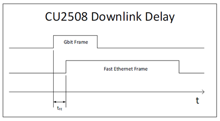
- In the uplink
FastEthernet X01..X04 to Gbit X09: tGE = 0.7 µs
FastEthernet X05..X08 to Gbit X09: tGE = 1.1 µs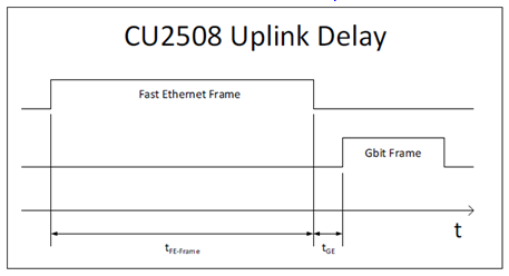
- These delays are therefore relatively insignificant compared to the other factors mentioned above. What is immediately apparent from the graphic, however, is the importance of the frame length and the necessary buffering in the uplink.
The CU2508-0022 as an EtherCAT slave
Each downlink port of the CU2508-0022 can be configured as a separate EtherCAT device, see chapter Configuration of a port as an EtherCAT port. In this case, the downlink port represents the first EtherCAT device in the system. It is Distributed Clocks-capable and can therefore serve as a reference clock in the segment.
By combining two such EtherCAT ports, the combination of EtherCAT cable redundancy and distributed clocks function is possible.
Time-controlled sending/receiving (in preparation)
The frame forwarding in the CU2508-0022 can be subjected to precise time control by the local clock:
- the driver or the user application specifies at which time and via which downlink port a frame is to be sent by the CU2508-0022.
This information is added to each frame by the driver as additional information. - each frame received by the CU2508-0022 at a downlink port is supplemented by receive information (receive port, time) and forwarded to the controller via the uplink.
The local hardware-based clock in the CU2508-0022 then controls the sending of the frames with a high temporal quality. This allows the CU2508-0022 to set up a real-time Ethernet network (network variables, Profinet, ...) even if the control device cannot guarantee hard real-time in the transmission of protocol data. However, the control device must be able to deliver or accept the data with sufficient speed.
The time control uses the 64-bit time format known from the EtherCAT distributed clocks system: resolution 1 ns and thus sufficient for approx. 584 years, starting from 01/01/2000 at 00:00.
The timestamp information (sending and receiving) is currently only evaluated by the CU2508 driver and is not available to the user application.
The SFD (Start of Frame Delimiter) is interpreted as the start of an Ethernet frame according to the IEEE802.3 standard.
EoE and TCP/IP
The CU2508-0022 is connected to the IPC via the Gigabit Ethernet interface. This interface appears in the operating system of the IPC with its properties (IP address, subnet mask, etc.). From the point of view of the operating system, there is therefore only this one network connection to which telegrams can be sent or from which telegrams can be received. The CU2508-0022 driver can now either forward data traffic at operating system level to a dedicated downlink port of the CU2508-0022 or feed it into the virtual switch (EoE). See also, for example, the documentation for EP6601-0002 or EL6601/EL6614. The selection is made via the setting in TwinCAT. Either the specific downlink port or EoE in general can be selected via “TCP/IP Port”.
See chapter Configuration of TCP/IP communication.
Applications
The above-described functions permit the use of the CU2508-0022 for the following applications, among others:
- Multi-EtherCAT adapter
Up to eight independent EtherCAT systems can be created. - Synchronized EtherCAT systems
If the CU2508-0022 is selected as the reference clock, the EtherCAT systems connected to the CU2508-0022 are operated with the same synchronized time base. - EtherCAT cable redundancy
Each two downlink ports of the CU2508-0022 can be combined to form a cable-redundant EtherCAT system. This means that fewer Ethernet ports are occupied on the controller, only one Gigabit Ethernet port is required for the uplink. This means that up to four cable-redundant EtherCAT systems are possible per CU2508-0022.
- EtherCAT cable redundancy with distributed clocks
Due to the common time base of the CU2508-0022, EtherCAT slaves that require distributed clocks are still subject to synchronization in the event of redundancy. - TCP/IP use without real-time
A downlink port on the CU2508-0022 can be configured as a non-real-time Ethernet port, or the CU2508-0022 operates in the Ethernet over EtherCAT (EoE) network and forwards TCP/IP frames from the connected EtherCAT systems.
- Real-time fieldbus to non-real-time controller
If an Ethernet-based fieldbus requires reliable constancy with regard to the sending of communication telegrams, low jitter is required in the cyclical operations of the controller. If a high-performance controller is able to process the cyclic operations with sufficient frequency (= required short cycle time), but the jitter, i.e. the regular interval between the cycles, is unacceptably high, the CU2508-0022 system as a real-time frame handler can provide the constant interval in frame transmission if the new data is available in the CU2508-0022 in time.
Data traffic in the lower-level EtherCAT segments
Ports X01 and X05 have a larger data buffer of 16 kB instead of the usual 8 kB for EtherCAT segments with particularly high data traffic.
“High data traffic” is generated by I/O systems with a lot of cyclic data, e.g. if many devices (over 100) and/or devices with large data requirements (e.g. analog oversampling terminals) are used.
If a “large” I/O system is operated in EtherCAT redundancy mode, it is advisable to use ports X01 and X05.
The memory situation found is reported by TwinCAT with “Cu2508 fifo sizes...”:
