Description
Task
The position lag monitoring function monitors whether the current position lag of an axis exceeds a limit. The difference between the output command value (manipulated variable) and the actual value reported back is referred to as the position lag.
∆s = sSoll - sIst
Monitoring takes place both at
- standstill and during
- motion of an axis.
At standstill, the axis can be moved out of the standstill position by application of external force to the mechanical system. As soon as the axis position exceeds the standstill tolerance window, the position lag monitoring function generates an error message (P-ERR-70081) and initiates corresponding measures for shutting down the axis.
When the axis moves, the dynamic position lag monitoring function calculates the permissible position lag for the current travel speed. If the permissible position lag is exceeded, an error message (P-ERR-70020) is issued and corresponding measures for shutting down the axis are initiated.
Prerequisites
If position lag monitoring has been selected, it is active only if
- the axis is being controlled (controller enabled) and
- slaving mode is not set for the axis.
Position lag monitoring can be used both for analog drives for which the CNC takes care of position control and for digital drives that perform position control themselves. If digital drives perform position lag monitoring themselves, monitoring can additionally be realized by the CNC. In most cases, however, this is no longer necessary.
Measures in the event of exceeding of the permissible position lag
The control initiates the position measures if the permissible position lag of an axis is exceeded:
- Output of an error message belonging to fault reaction class 5 [DIAG]
- The affected axis is stopped with deceleration that can be set in the axis parameter list.
- All axes that are interpolated with the affected axis in the contouring combination are stopped.
- The PLC can take further measures via the control interface.
Methods
The NC control offers two methods with which the maximum permissible position lag is calculated:
- Type 1: standard method
- Type 2: linear method
- Type 4: velocity independent method
The position lag can be monitored with all methods during standstill. The permissible position lag of a moving axis is calculated in the first methods depending on the set speed. The standard method (type 1) uses a parameter-definable filter. The linear method (type 2) is based on the theoretical position lag, which can be enlarged up to a factor of 2. With both methods, the permissible position lag can be shifted in time via a timer.
With method 4 even for a moving axis the position lag is checked against a velocity independent constant value. This method is useful for axes that use feedforward.
Parameterization
Position lag monitoring can be parameterized individually for each axis by means of axis parameter settings.
Switching on/off
Position lag monitoring is switched on or off with the P-AXIS-00172 parameter (parameter = 0). When monitoring is off, no maximum permissible position lag is calculated, and no error message is issued.
Selection
The position lag monitoring type is set with the P-AXIS-00172 parameter. The position types of position lag can be parameterized:
- No position lag monitoring
- Type 1: standard method
- Type 2: linear method
- Type 4: velocity independent method
Deactivating reaction
To set position lag monitoring, it is necessary to calculate and display the limit without monitoring taking place. A reaction by position lag monitoring is deactivated for this purpose. However, the permissible position lags are still calculated and displayed with the chosen method. However, violation of the permissible position lag does not result in any reaction by the control and above all serves to parameterize position lag monitoring during commissioning.
Position lag monitoring is deactivated by setting the P-AXIS-00176 parameter to the value 1.
Causal system, system run time
The theoretical position lag ∆s depends on the set speed v and the gain factor Kv as follows.

On the real axis, however, there is a real position lag, which has a delay with respect to the theoretical position lag. This delay is caused by a system-related cycle shift in the control system's position controller and by the system's mechanical time constant (Figure 1).
As the methods for calculating the permissible position lag do not take this influence into account, the permissible position lag can be shifted with an additional timer (PT1). This timer is parameterized with the P-AXIS-00170 parameter.
 Fig.1: Shifting the real position lag
Run time with digital drives
In the case of a digital drive, the NC can additionally perform position lag monitoring. Due to the run time of a drive bus and processing in the drive itself, after output of the command value the actual value is only read in by the CNC a few cycles later. In this case, it is important that the position lag is determined as the difference between command values and actual values that belong together in terms of timing.
The delay is specified with the P-AXIS-00191 parameter.
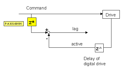 Fig.2: Delaying of the command values for calculation of the position lag